With the last update, the Define Paper Size function was added to OCAD. The paper size is visible in the drawing area and the area outside is grayed out.
In the last OCAD Update, small but useful changes were added to the Course Setting Module.
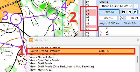
Show Preview The shortcut CTRL+R has been added to show / hide the Preview mode. (1)
Highlight unused control in course object list Controls that are not used in any courses will be highlighted with red color in the course object list. (2)
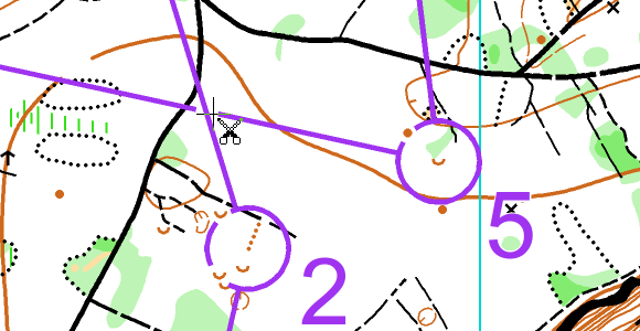
Cut out control circles and connection lines Select a control circle or course line and use the shortcut CTRL+G to cut a gap.
To create a gap, click once on the control circle or course line. Also, you can click and drag the mouse from the beginning to the the end of the part that should be cut out.
To close a cut, click into the gap again.
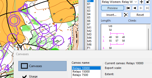
Canvas Relays are now also supported in the Canvas function.
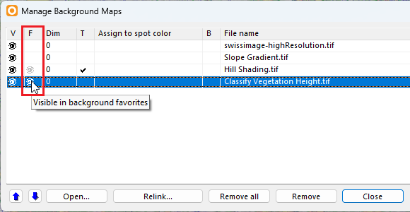
Thanks to the Background Favorites option, you can quickly and easily switch between different background maps when drawing.
In the Manage Background Maps dialog, you can make a background map visible in the background favorites by turning on the eye icon in the corresponding cell.
In this example, four different background maps are loaded: An areal image, a slope gradient map, a hill shading map and a vegetation height map. The last two are marked as background favorites.
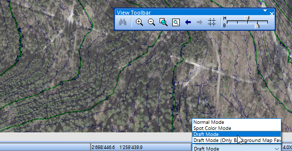
As you know, the topmost visible background map is displayed in OCAD. In this example, the aerial image is therefore displayed, when we switch to Draft Mode.
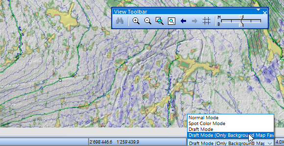
If you now switch to the Draft Mode (Only Background Map Favorites), the two background maps marked as background favorites are displayed (in our example the hill shading map and the vegetation height map). The hill shading has been set as transparent so that both files are visible together.
You can switch the View Mode in the Status Bar (see image above) or in the View menu. You can also set a Shortcut to quickly navigate through the different View modes, e.g. Alt + V.
Which View modes appear in the loop can be set in the OCAD Preferences. For example, if you are not working with Spot colors, you can omit this mode.
OCAD has updated its symbol sets for orienteering and sprint orienteering after a revision by the IOF.
The new symbol sets are valid from 1st February 2024 and mandatory for IOF events from 1st January 2025.
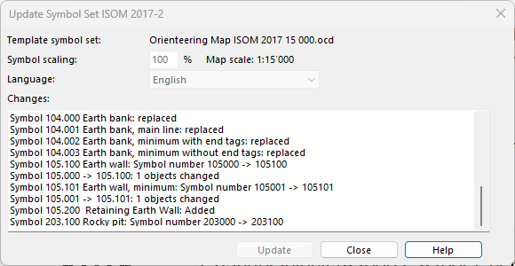
Update Orienteering Symbol Set due to ISOM 2017-2 Revision 6
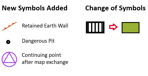
The most important changes:
New symbol added for Retained earth wall | New symbol added for Dangerous pit | New symbol added Continuing point after map exchange | Renumbering of certain symbols | Certain symbols for minimum sizes removed
Update Sprint Orienteering Symbol Set due to ISSprOM 2019-2 Revision 6
The most important changes:
New symbol added for Retained earth wall | New symbol added Continuing point after map exchange | New symbol added Area with obstacles | New symbol added Area runnable at lower level (521) |Renumbering of certain symbols | Certain symbols for minimum sizes removed
How to update your maps to the new specifications?
In OCAD, you can update a map drawn with ISOM 2017-2 or ISSprOM 2019-2 to the latest symbol set by using the function Update Symbol Set.
For maps that are drawn with an older symbol set, use the function Symbol Set Conversion. Check the page Symbol Set Overview to find out which symbol set you are using.