In this article we present different ways of drawing stairs in OCAD and what to look out for.
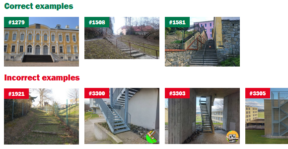
If stairs are drawn too small or too narrow, this greatly impairs legibility and the staircase can easily be mistaken for an impassable object (especially if the print quality of the circles is poor).
How is the stairway symbol defined?
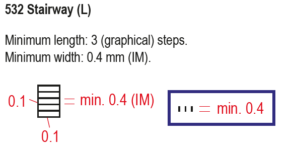
Steps of a stairway shall be represented in a generalized manner. Contour lines shall be cut out for better legibility, if they touch stairways.
This means that when you are drawing stairs you should make sure that…
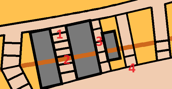
- (1) treads are not drawn with too little spacing (min. 0.4mm)
- (2) contour lines are cut out
- (3) stairs are not drawn too narrow (min. 0.4mm)
- (4) more than 2 steps are drawn (min. 3)
By the way: In addition to the symbol definition, the IOF O Map Wiki also contains images with correct and incorrect examples.
Draw steps individually or use stairway symbol
There are basically two ways to draw steps:
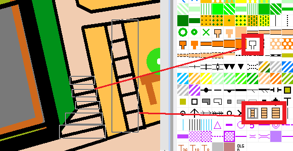
- Use the symbol Step or edge of paved area (symbol 501.100) to draw steps individually
- Use the symbol Stairway (symbol 532.00) to use a predefined stair width.
Use stairway symbol
The stairway symbol is suitable for straight staircases. The minimum width and tread width comply with the IOF specifications. The stair filling (colour. 44 Brown 30% – stairs) covers the contour lines, so no cutting of contour lines is needed.
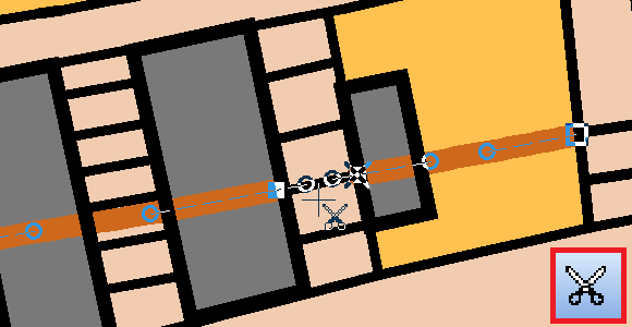
Problems arise with curved staircases (2) or staircases with varying widths. Often the predefined width does not fit and leads, for example, to thick edges (3). In such a case, the predefined stair symbols can be duplicated and the width changed afterwards. The whole width of the staircase should be visible and if not, building, walls, etc., should be reduced in size (4).
When drawing, it is also important to note that the beginning and end of the stairs (1) must be examined and edited if necessary.

Draw steps individually
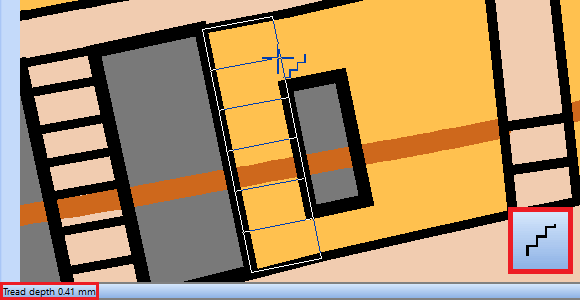
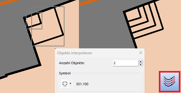
You get the most flexibility when you draw steps individually. For that, you can use the symbol Step or edge of paved area (symbol 501.100).
- With the Stairway mode you can easily specify length, width and now also the tread depth (step distance). This is displayed at the bottom left of the status bar.
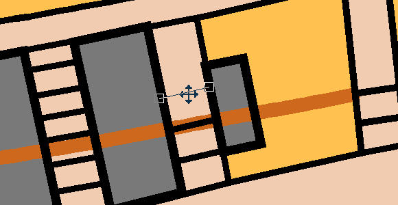
- Individual steps can be copied (Ctrl + C), pasted (Ctrl + V) and moved to the correct position with the mouse or arrow key.
- The Interpolate Objects function can also be useful to draw steps.
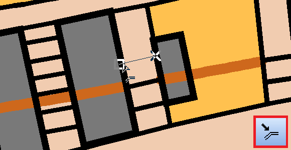
- With Move Parallel and simultaneously pressed Ctrl + Shift key, stairs or line objects can be moved in parallel and duplicated at the same time.
- To cut contour lines, use the Cut icon. A virtual gap can be inserted by holding down the Ctrl key.