To draw objects in OCAD, a drawing mode must be selected.

Probably the two most commonly used are the Curve mode (e.g. to draw contour lines) or the Straight line mode (e.g. for buildings).
The simplest way to draw objects in OCAD is to mix these two drawing modes.
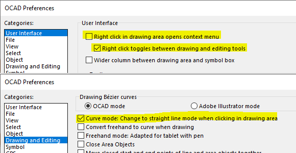
First, the following settings must be made.
- Activate Right click toggel between drawing and editing tools in the OCAD Preferences > User Interface categorie.
- Activate the option Curve mode: Change to straight line mode when clicking in drawing area in the OCAD Preferences -> Drawing and Editing categorie.
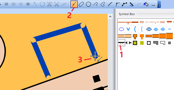
Let’s draw something! It’s as simple as that:
- Select an area or line symbol (1)
- Choose the Curve mode (2)
- Click in the drawing area. (3)
- Each additional click inserts a new vertex.
- Right-click to finish the object.
- Right-click again to draw a new object.
You can also click+drag the cursor to draw a Bézier curve.
As you will notice, this way of drawing is very simple and intuitive.
However, in contrast to the Straight line mode, Normal vertices and no Corner vertices are inserted. This can lead to different representations of line objects.
It is recommended to visually check the line objects and possibly change the vertex types.

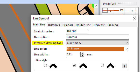
Note: For each symbol, you can define a Preferred Drawing tool. You can change the settings by right-clicking on a symbol in the symbol box.