The specifications for the control descriptions have been slightly adapted by the International Orienteering Federation IOF and published as ISCD 2024.
The new symbol sets are valid from 1 January 2024 and are already available in OCAD (Menu File > New > Course Setting project for orienteering).
The most important changes:
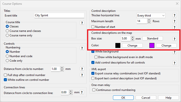
Color of the control description on map now black by default (optionally still purple, see the Course Setting Options).
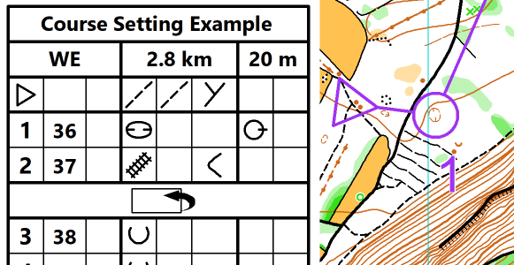
According to IOF, control description sheet on map should be printed in black. New symbols for map filp and railway are shown.You can change the color of the control description in the Course Setting Options either to black or purple.
New symbol added for a map flip (turn the map over).
In this article we present different ways of drawing stairs in OCAD and what to look out for.
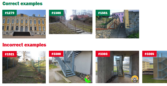
If stairs are drawn too small or too narrow, this greatly impairs legibility and the staircase can easily be mistaken for an impassable object (especially if the print quality of the circles is poor).
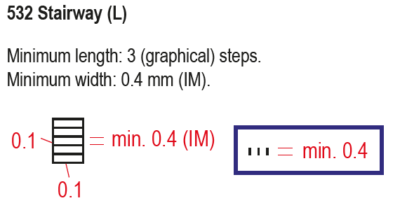
How is the stairway symbol defined?
Steps of a stairway shall be represented in a generalized manner. Contour lines shall be cut out for better legibility, if they touch stairways.
This means that when you are drawing stairs you should make sure that…
(1) treads are not drawn with too little spacing (min. 0.4mm)
(2) contour lines are cut out
(3) stairs are not drawn too narrow (min. 0.4mm)
(4) more than 2 steps are drawn (min. 3)
By the way: In addition to the symbol definition, the IOF O Map Wiki also contains images with correct and incorrect examples.
Draw steps individually or use stairway symbol
There are basically two ways to draw steps:
Use the symbol Step or edge of paved area (symbol 501.100) to draw steps individually
Use the symbol Stairway (symbol 532.00) to use a predefined stair width.
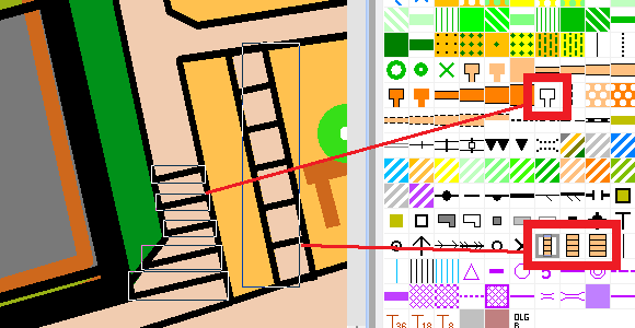
Use stairway symbol
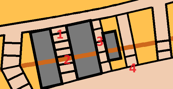
The stairway symbol is suitable for straight staircases. The minimum width and tread width comply with the IOF specifications. The stair filling (colour. 44 Brown 30% – stairs) covers the contour lines, so no cutting of contour lines is needed. Problems arise with curved staircases (2) or staircases with varying widths. Often the predefined width does not fit and leads, for example, to thick edges (3). In such a case, the predefined stair symbols can be duplicated and the width changed afterwards. The whole width of the staircase should be visible and if not, building, walls, etc., should be reduced in size (4). When drawing, it is also important to note that the beginning and end of the stairs (1) must be examined and edited if necessary.
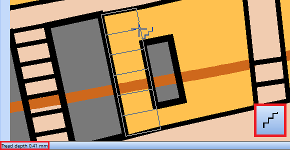
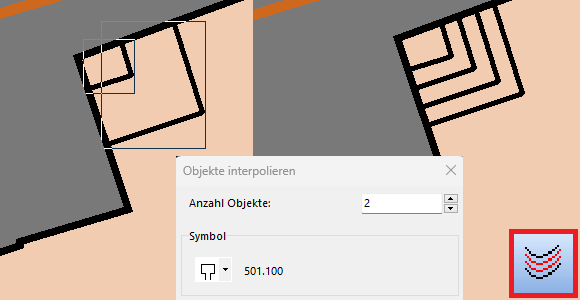
Draw steps individually
You get the most flexibility when you draw steps individually. For that, you can use the symbol Step or edge of paved area (symbol 501.100).
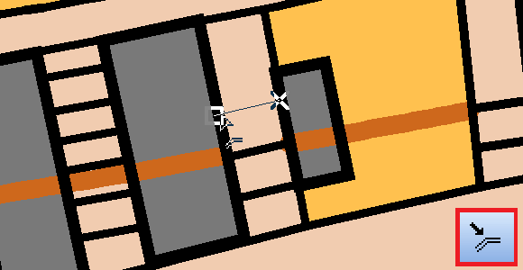
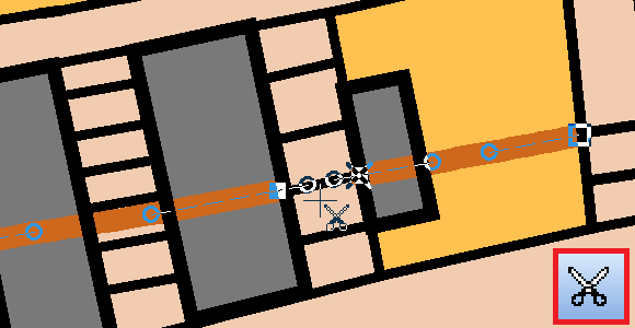
With the Stairway mode you can easily specify length, width and now also the tread depth (step distance). This is displayed at the bottom left of the status bar.
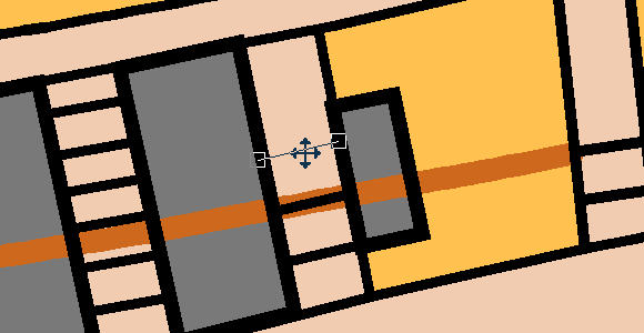
Individual steps can be copied (Ctrl + C), pasted (Ctrl + V) and moved to the correct position with the mouse or arrow key.
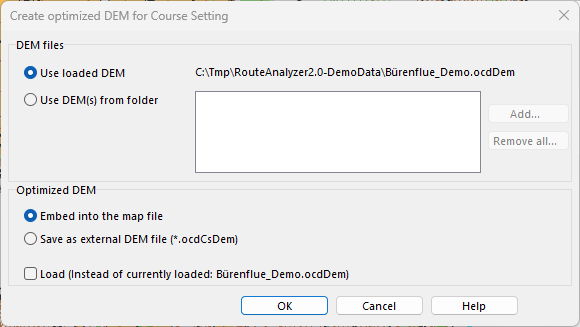
To use the OCAD Route Analyzer 2.0, course setters need a current map as well as a Digital Elevation Model (DEM).
This is loaded into the map or course setting file and ensures that the climbing and slope gradient are included in the route calculation. The DEM is typically created by the cartographer and has traditionally required a lot of memory.
The DEM can now be optimized and compressed without loss of quality for route calculation. This significantly reduces the file size of the DEM and makes it easier to share. The optimized elevation model can also be embedded directly into the map or course setting file, as is already possible with layout images.
On mobile devices, you can zoom in and out at will. Zooming in is appreciated by the map makers as it allows more precise drawing and sketching and more accurate display of the background map.
However, by zooming in and out, map makers are not working at a fixed scale and so the sense of distance within the map is lost. This was easier when mapping with pen and paper where the scale was fixed.
A few things can be done to improve the feeling for the scale on a mobile device:
Working with the OCAD Sketch App
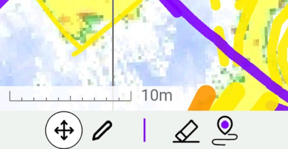
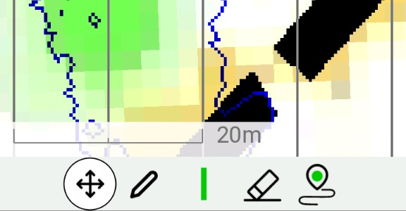
Make use of the scale bar that has been added in the latest update of the app. The scale bar can be turned on or off in the settings.
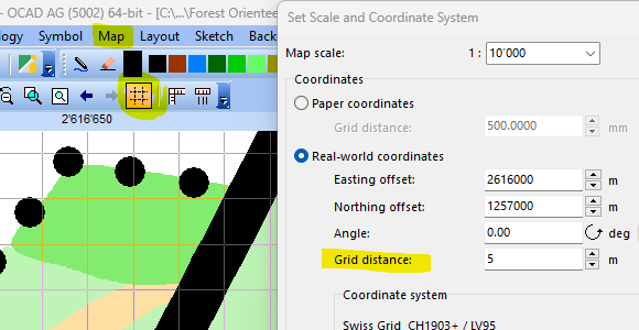
Adjust the distance between the north lines. You can do so in the settings. E.g., set it to 1mm in a project with a 1:10’000. This gives you every 10 meters a line. In a 1:4’000 project, use 2.5mm to get a line every 10 meters.
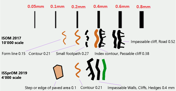
Know the different line widths. It is advantageous to know the line widths and to sketch objects accordingly. E.g., an impassable wall on a sprint map with a line width of 0.4mm and contour lines with a line width of 0.21mm.
In OCAD Desktop, it is also possible to check directly during drawing whether the drawn line or area object corresponds to the minimum dimension of the IOF, as we explain in this blog post.