Tag Archives: Orienteering Map Making

OCAD Route Analyzer 2.0 Released

The OCAD Route Analyzer 2.0 has been released as a beta version.

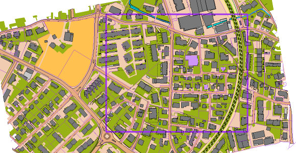
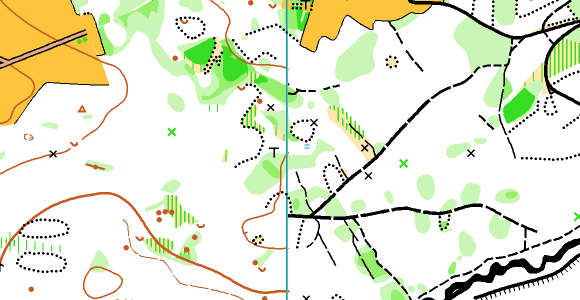
Thanks to the consideration of runnability and relief, the Route Analyzer 2.0 can find the fastest routes between two controls in urban as well as in classic forest terrain.

The fastest calculated routes (blue) and alternatives (red).

The previous version of the Route Analyzer is limited to 2D sprint maps, because it assumes a constant speed and only distinguishes between passable and impassable map objects. The shortest route is displayed as the result.

Comparison between the old and the new version of the Route Analyzer. The left route option is shorter, but has more meters to climb than the right option.

Consideration of runnability and relief

To find the fastest route, the Route Analyzer takes into account the distance, the relief and the runnability.

Therefore, resistance values are assigned to the individual map symbols. These are based on assumptions and can be changed in the settings. It is well known that the forest is not equally runnable depending on region and season.

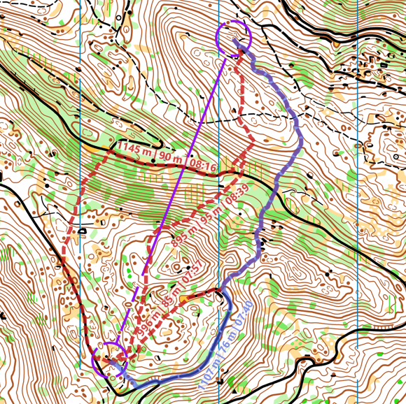
The influence of the relief must be divided into two factors: The difference in altitude in the running direction and the slope transverse to the running direction. The latter causes a reduced speed when running along a steep slope.

In order to take the elevation into account, a DEM has to be loaded. For runnability, each OCAD symbol is assigned a resistance value, which can be adjusted manually.

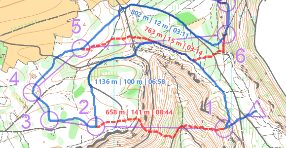
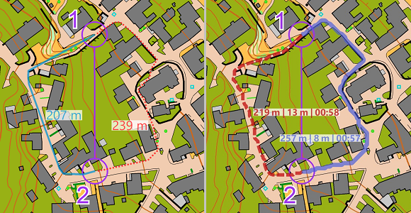
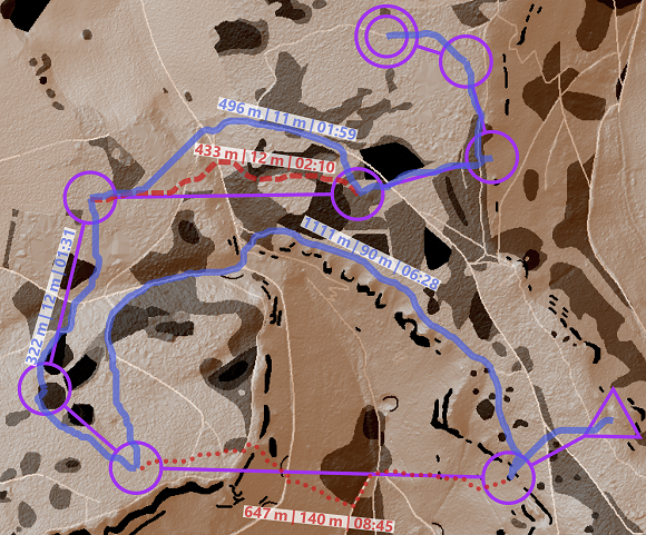
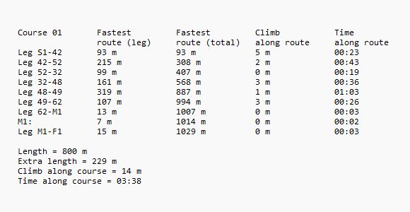
Taking these influencing factors into account, the algorithm calculates the fastest route from one control to the next. Alternative routes can be added with via points, which are mandatory to pass. In OCAD, the distance, climbing and expected running time are displayed for each route.

The fastest calculated routes (blue) and alternatives (red) in the WOC 2023 Women Relay.

Up-to-date map symbols and elevation model required

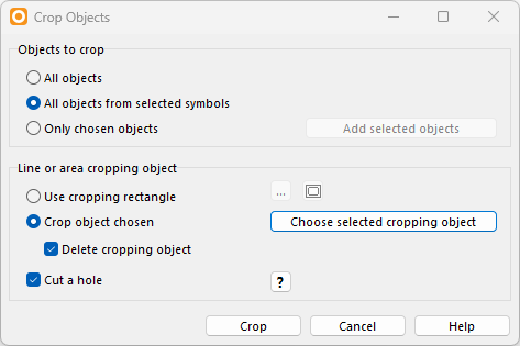
A prerequisite for correct functioning with the new calculation method is a map with a current set of symbols and a digital elevation model (DEM). When assigning the resistance values, OCAD accesses the map symbols. If their properties (symbol number, color values, line thickness, etc.) are within a range defined by OCAD, an assignment is made. An up-to-date symbol set that complies with the specifications of the International Orienteering Federation is therefore advantageous.

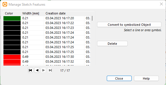
The DEM is normally created by the map maker to calculate e.g. contour lines or a hill shading map. Newly, the DEM can be more easily passed on to the course setters as an optimized and compressed Course Setting DEM (ocdCsDem) due to the greatly reduced file size, or even directly embedded into the map file or course setting file.

Resistance Layer and hill shading map.

Many application possibilities

Thanks to the relative time difference between route variants, the Route Analyzer 2.0 can be used as an aid for planning exciting route choices in all orienteering disciplines. In addition, it can be used to calculate distance, amount of climbing and expected running time along the ideal route of an entire orienteering course at the push of a button. Besides, the Route Analyzer 2.0 can also point out undesirable or dangerous routes, e.g. due to missing restricted areas or unclearly drawn maps.

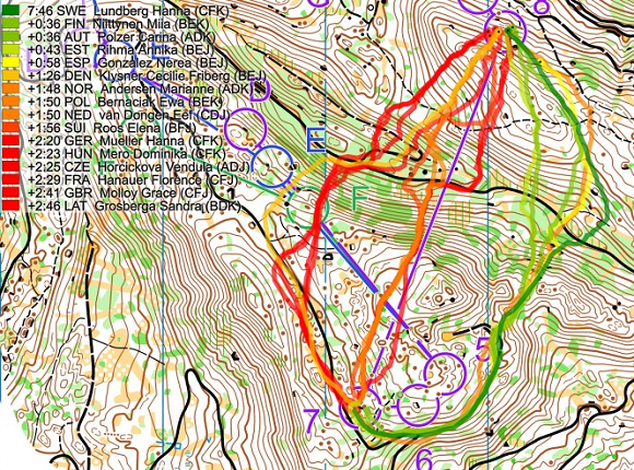
Whether the displayed route is actually the fastest route depends on individual factors such as personal strengths, in addition to those already mentioned such as region and time of year. With the help of GPS routes, the fastest route can be determined in retrospect or at least guessed. Nevertheless, it is exciting to compare the personally favored routes with the calculated results.

Route comparison by Jan Kocbach (World of O) WOC 2023 Women Relay.

Crop Objects

The Crop Object funtion in OCAD offers many possibilities, such as cropping a map or deleting certain objects in an area.

Here are a few examples:

A map should be cropped to the extent of the purple line object. You can also use a cropping rectangle instead of selecting a crop object, see Settings below.
Map has been cropped to the extent of the chosen crop object.
Settings
  • Create a hole
    Use this method to cut away parts of the map.
A map where the part of the purple line object is to be cut away.
Cropped map
Settings. Note that Cut a hole is activated.
In the left part, all smaller paths and roads were cut. In the right part all terrain objects like contour lines, knolls or depressions.

Special: Crop Text
You can also use text objects as cropping objects. Just convert them first into Graphic Objects in the Object menu.

Choose a text symbol and add a text.
Select the text object, go to menu Object>Convert into Graphic Object.
Select each graphic object and use it to cut a hole into the map.

OCAD Team: From Cartographers for Cartographers

At OCAD, we not only develop and maintain the OCAD software, but we are all active cartographers, course setters, and map controllers. Almost all of us.

OCAD Team from left to right: Hubert, Gian-Reto, Andreas, Rahel, Alistair, Thomas

Gian-Reto Schaad is a very experienced cartographer and member of the Swiss Orienteering Map Commission, who completes every year several smaller and large mapping projects using his Windows tablet. Furthermore, he is responsible for the layout and print preparation of all maps for the Swiss O Week 2023.


Hubert Klauser, also a member of the Swiss Orienteering Map Commission, is doing several maps each year, such as the very demanding Kernwald earlier this year. Developing the OCAD Sketch App and at the same time test it extensively in the field went hand in hand.


Andreas Kyburz has also recently been involved in major mapping project, where he felt  in love with the OCAD Sketch App. The former member of the Swiss National Orienteering Team also likes to set challenging courses for training and competitions. The OCAD Route Analyzer helps him with this.


Thomas Gloor concentrated mainly on being map chief and map consultant for the region of Northwestern Switzerland after a long period of activity for both the IOF and the Swiss Map Commission.


Alstair Landels is our new employee at OCAD since June this year. As a former World Cup winner (1994) he knows how to set interesting courses for orienteering races. With Alistair, the OCAD team becomes more international. Born in New Zealand, Alistair lives and works in England.

Rahel Lozano is our accountant and has nothing to do with cartography and orienteering. She makes sure that the orienteering freak show doesn’t get too out of hand by talking about normal life.

Manage Sketch Features

In OCAD you can draw sketches directly using the Sketch toolbar or import them from the OCAD Sketch App via the OCAD Sketch App Data Exchange tool.

What is the best way to manage these sketches? How do I make sure that I draw all sketches?

Manage Sketch Features
All sketches are listed in the menu Sketch > Manage Sketch Features.
When a sketch is selected in the list, the OCAD drawing area is centered on it.

Manage sketch features dialog.

Show Sketches
Under Menu Sketch > Options there are different display options that make sense depending on the situation. We recommend testing different transparency and opacity settings, e.g. if sketch features should be behind map objects or not.

Sketch options dialog.
  • Opacity: An sketch feature opacity of 100% will cover the map objects behind it.
Opacity 100%, transparent unchecked, display sketch layer behind map unchecked.
Opacity 70%, transparency off, display sketch layer behind map unchecked.
  • Transparent: If the rendering of the sketch features is slow, the transparency should be turned off.
Opacity 70%, transparency on, display sketch layer behind map unchecked.
  • Display sketch layer behind map: We recommend to activate this option during the final drawing. For mapping in the terrain with a Windows tablet and OCAD Desktop, it’s better to have the sketches before the map. In the OCAD Sketch App, the Sketch layer is always before the map.
Display Sketch Layer before map. Transparency off.
Display Sketch Layer behind map. Transparency off.

Hide sketch features: All sketches can be hidden in the toolbar or under menu Sketch > Hide. Advanced users can also use a Shortcut.

Delete Sketches
The following options are available for deleting sketches.

  • Eraser
    The eraser in the sketch toolbar can be used to erase sketch features completely or partially. In contrast to custom OCAD map objects no preliminary feature selection is needed for this. Depending on the zoom level, sketch features can be erased with varying degrees of coarseness. Zoom out to quickly delete features over a large area.
  • Delete All Sketch Features
    The function in the menu Sketch > Delete All Sketch Features deletes all sketch features.
  • Manage sketches
    Sketches can be deleted individually in the menu Sketch > Manage Sketch Features.
Different ways to delete sketches.

Visual Inspection
At the end of the final map work, the question arises: Have I worked through all my sketches?
In case the sketches were deleted or erased during the final map work, you can check the list under Sketch > Manage Sketch Features.

If the sketches were not deleted during the final map work, a visual check is necessary. To make the sketches clearly visible, the map and background maps can be displayed transparently or not at all.

  • Switch to Draft mode and use the slider in the View toolbar to set the opacity of the map (M) and background map (B) to the far left.
  • Alternatively, you can hide the map and the background map (menu Map > Hide; menu Background Map > Hide All).
Sketch features with hidden map.

6 Tips to Edit Vertices

Vertices are used to define the position of points, lines and areas. In this blog post we will show you how to edit vertices in the most efficient way.

#01: Set mark size large enough

First, make sure that the size of the vertices is large enough. You can change the mark size and mark color in the Drawing and Editing section in the OCAD Preferences. In the same section, you can also scale the size of the mouse cursor.

#02: Move vertices

To move a vertex, select the Select Objects and Edit Vertex icon in the Edit and Drawing Toolbar and drag the vertex to the new position. Double click on a vertex and move it then with the arrow keys. Instead of moving a single vertex, you can also click on a segment (section between two vertices) and drag it.

#03: Add and remove vertices

You can use the icons in the toolbar to add or remove vertices (see picture below).
However, you should definitely know these two shortcuts.

  • A Vertex can also be added, when you press the Shift and Ctrl key simultaneous while clicking on the object.
  • A Vertex can be removed, when you press the Ctrl key while clicking on an existing vertex.
  • Hold down the Ctrl key and the left mouse key while moving over the vertices to remove multiple vertices, e.g. to smooth buildings from imported cadastral data. The mouse movement works like an eraser for the vertices of the selected object.

#04 Toggle between vertices

Toggle between the different vertex types (normal vertex – dash vertex – corner vertex) with pressed Ctrl+Space key and click on a vertex.

#05 Edit vertices and tangents of Bézier curves

If you draw a Bézier curve and are unhappy with the last vertex drawn, simply click the backspace key. The last tangent will be deleted and you can try again. You can delete as many tangents as you like up to the beginning of the line. The last two tangent end points can also be edited while drawing.

#06: Get faster into the edit mode

Select the following settings as shown below in the OCAD Preferences. When you draw an object, right-click to close it and get to edit mode. Another right-click switches back to drawing mode.

More OCAD Tips and Tricks

Visit the OCAD Wiki page Tips with Keyboard and Mouse to further optimize your drawing and editing skills in OCAD.