OCAD Preferences
The OCAD Prefernces can be set in the Options menu.
Some preferences are not available in the OCAD Starter and OCAD Course Setting editions.
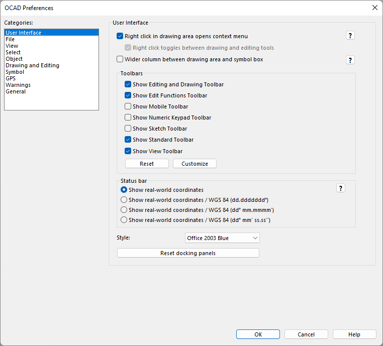
GUI (Graphical User Interface)
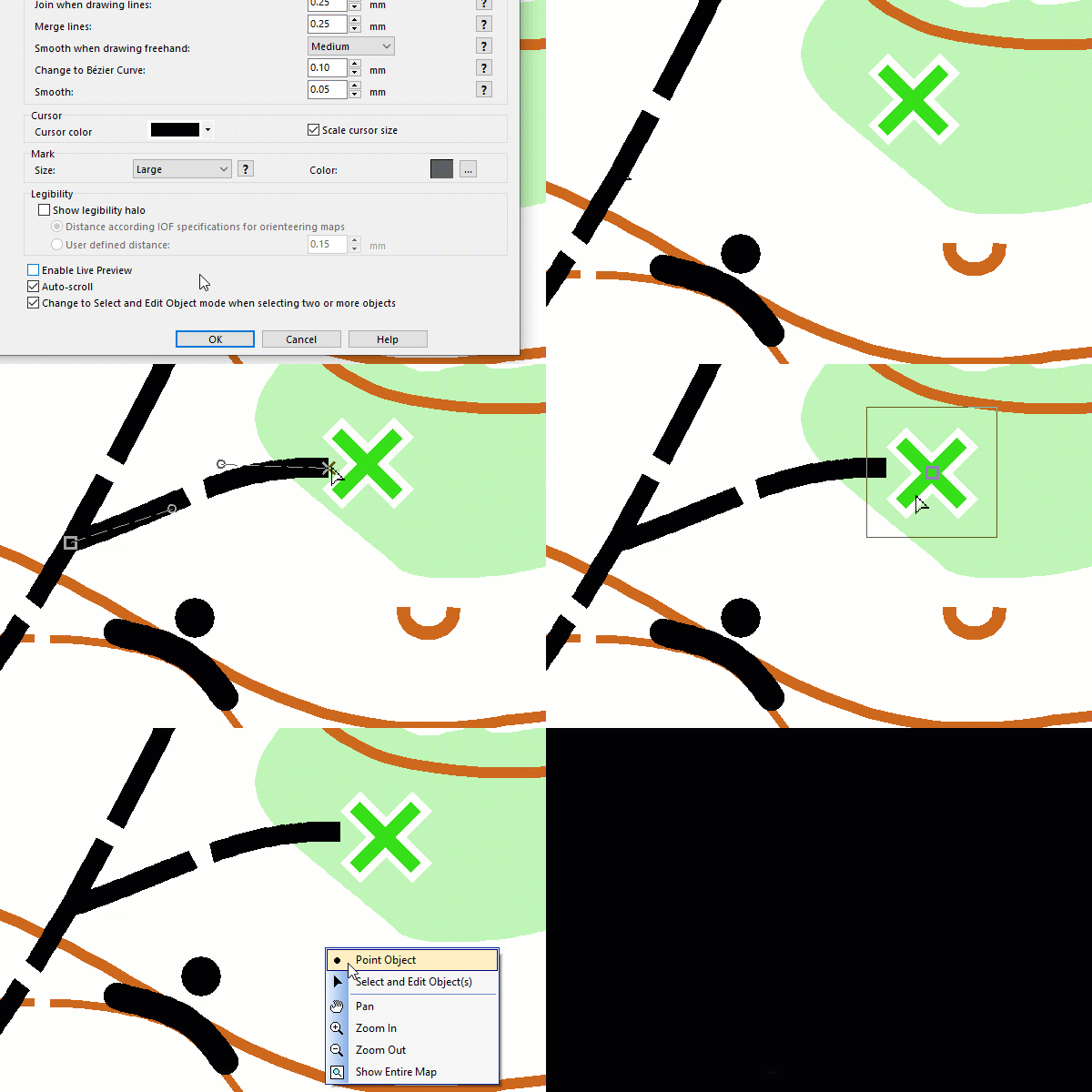
If enabled, the context menu is shown by clicking on the drawing area with the right mouse button.
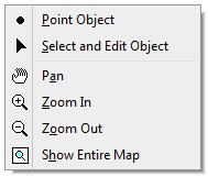
In the upper part of the Context menu, you can switch between the current Drawing Mode, the Select and Edit Object mode and the
Select Object and Edit Vertex mode.
In the lower part of the Context menu, you can change the view either with the Pan,
Zoom In,
Zoom Out or the
Show Entire Map tool.
If disabled, you can switch between the current Drawing Mode and the Select Object and Edit Vertex mode by clicking on the drawing area with the right mouse button.
Right mouse click toggles between drawing and editing tools
This option is only activated if the Context menu in drawing area option is deactivated.
We recommend to deactivate this option when drawing on a tablet with a pen. In this case OCAD ignores the right click during drawing.
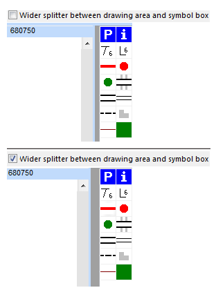
Wider splitter between drawing area and symbol box
If this option is enabled, the splitter between the symbol box and the drawing area appears wider as usual. This feature may improve the user-friendliness.
Toolbars
Show or Hide the following toolbars in this field:
- Editing and Drawing Toolbar
- Edit Functions Toolbar
- Mobile Toolbar
- Numeric Keypad Toolbar
- Sketch Toolbar
- Standard Toolbar
- View Toolbar
Click the Reset button to reset the toolbar positions to the default settings. Please restart OCAD for the changes to take effect. This function is sometimes used if an undocked toolbar outside the screen.
Click the Customize button to add or remove icons to/from the toolbars.
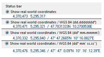
Status bar
Choose the format of the coordinates appearing in the Status Bar in this box.
Style
Change the virtual appearance of the GUI by choosing one in the dropdown list.
Reset docking panels
Reset the docking panels (symbol box, GPS box and database box). OCAD restart needed to take effect.
Use this function if the symbol box is hidden.
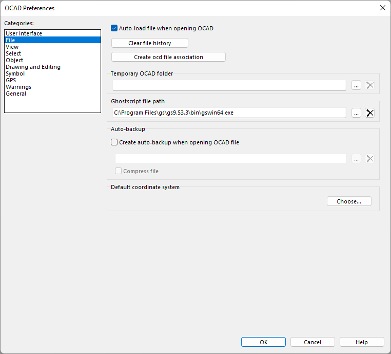
File
Auto file load when opening OCAD
Check this box to load the last map you worked on automatically when OCAD is started. Otherwise no map will be loaded.
Clear file history
Click this button to clear the file history from Recently Exported Documents and Recently Used OCAD Files. If a drive from the file history files does not exist anymore, e.g. disconnected network drives, it may needs more time to open the File menu. This function solves the problem.
Create ocd file association
Click this button to associate the running OCAD edition with .ocd files. OCAD must run as administrator to execute this function (change file association in Windows Registry).
Confirm to run as administrator.
Alternatively, go to Settings>Apps>Default apps and Chosse default apps by file type.
![]() Normally, default file type for .ocd files is set during installation. However, if you run OCAD in the Cloud, the default file type is not set.
Normally, default file type for .ocd files is set during installation. However, if you run OCAD in the Cloud, the default file type is not set.
Temporary OCAD Folder
While working on an open file OCAD is saving all changes to temporary file(s) in a tmp folder. This folder can be changed here. By default it is C:\Users\[USERNAME]\AppData\Roaming\OCAD\tmp.
OCAD saves the WMS images in this folder.
Ghostscript File Path
OCAD using Ghostscript to converting a pdf background map to a jpg file when opening the pdf file.
Download and install Ghostscript.
After the installation click the Choose (...) button to set the file path of the Ghostscript exe program file (e.g. C:\Program Files\gs\gs9.55.0\bin\gswin64.exe).
Auto-backup
Activate the checkbox Create auto-backup when opening OCAD file and every time you open an .ocd-file, OCAD will save a backup of this file. You can also create a backup manually by using the Create Backup funktion in the File menu.
Click the Choose button to set a file path for the auto-backup.
Activate Compress file to save disk space.
![]() Remember to clean out the auto-backup directory from time to time.
Remember to clean out the auto-backup directory from time to time.
Default coordinate system
Set here the default coordinate system for your template files.
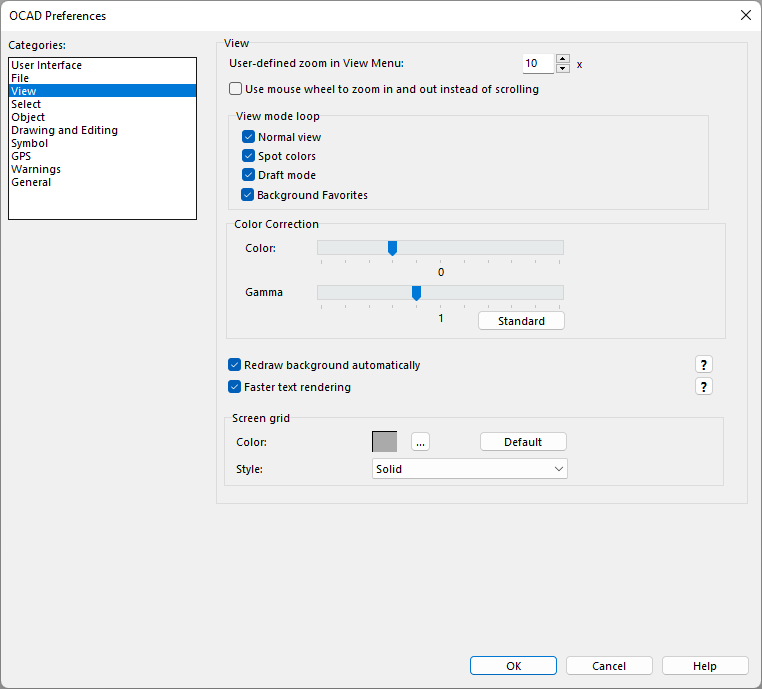
View
Enter a value to specify the User Defined Zoom. Choose User Defined in the View menu to apply the specified zoom to the map.
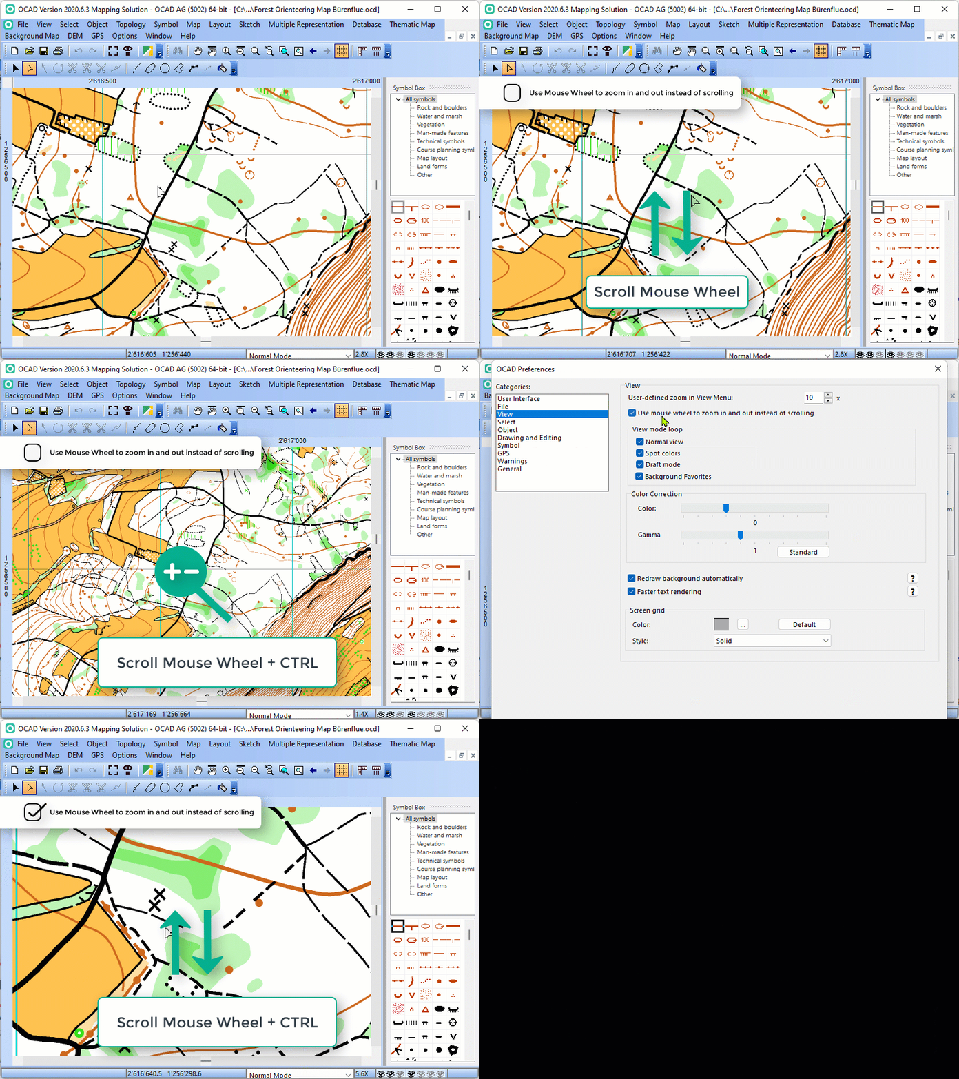
Use mouse wheel to zoom in and out instead of scrolling
Use mouse the wheel to zoom in and out instead of scrolling.
Use CTRL + mouse wheel for vertical scrolling.
Use CTRL + SHIFT + mouse wheel for horizontal scrolling.
View mode loop
With the View mode loop tool you can easily switch between different view modes. Select the view modes you want to switch between in the View mode loop box in the View category of OCAD Preferences.
To use the View mode loop you have to define a Shortcut for View - View Mode Loop. Afterwards you can switch between the set view modes using the Shortcut.
Visit the View Mode Loop article to get more information about this function.
Color Correction
On some monitors colors and gamma of the map are not displayed correctly. Use the controller to regulate the color and gamma manually. Click on the Standard button to set the Color Correction back to default.
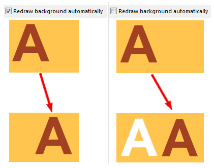
Redraw background automatically
If this option is enabled, the map is redrawn after every single modification of the map (This may reduce the performance of OCAD). Otherwise you have to press the F5 key or select Redraw in the View menu to redraw the map.
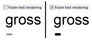
Faster text rendering
Enable the Faster text rendering option to render text faster and less precisely. This may increase the performance of OCAD.
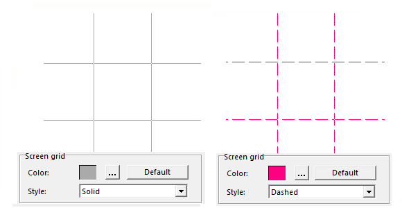
Screen Grid
In this section of the OCAD Preferences the color and the appearance of the Screen Grid can be changed.
Change the Color by clicking the Setup icon.
Click the Default button to reload the default gray color.
Choose a Style from the dropdown menu. The Screen Grid can either be Solid, Dashed or Dotted.
Select
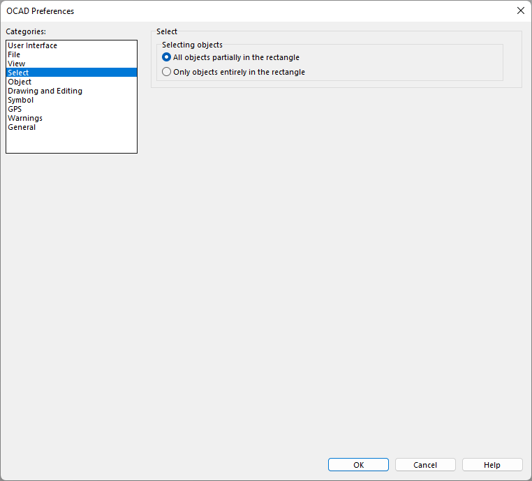
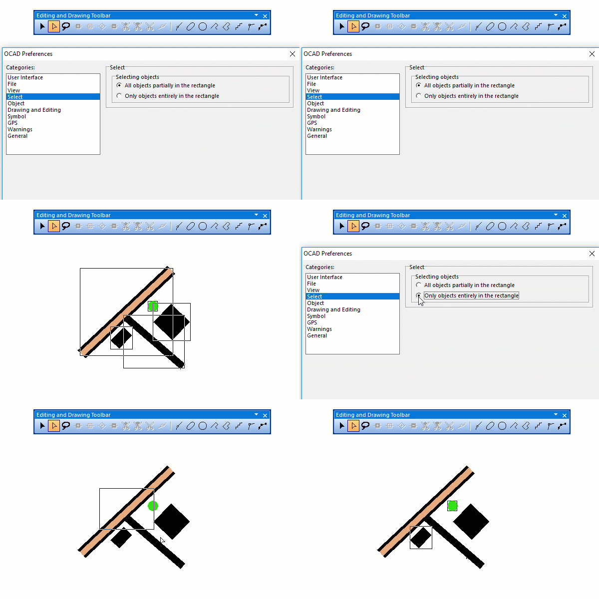
You can choose between two modes to select multiple objects:
- All objects must be with at least one vertex in the selection.
- All objects must be completely in the selection.
You can find more information about selecting multiple objects on this page: Select and Edit Multiple Objects.
Object
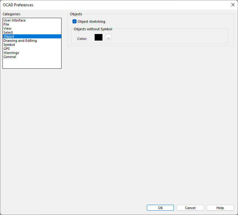
Object stretching
If this option is activated, you are able to stretch objects in the Select and Edit Object mode.
You can find more about stretching objects on this page: Select and Edit Object.
Unsymbolized objects
Choose a color for Unsymbolized Objects by clicking on the Setup icon. The Color Picker dialog appears and you can configure the color.
Drawing and Editing
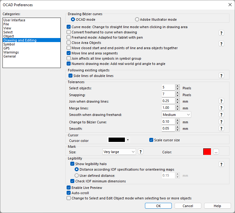
Drawing Bézier curves
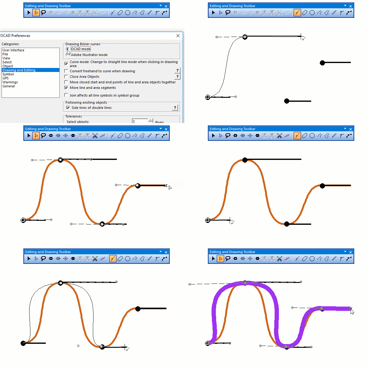
Choose the preferred mode for drawing curves.
- In OCAD mode, only the direction of a dragged tangent is used. The distance from the normal vertices to the curve vertices is calculated automatically. This is the recommended mode.
- In Illustrator mode, the length of the dragged tangent is used to calculate the distance of the curve vertex.
You can find more about drawing curves on the following page: Draw a Curve
Curve mode: Change to straight line mode when clicking in drawing area
Check this box to draw straight lines also in curve mode. See more in Change to Straight Line Mode
Convert freehand to curve when drawing
Check this box to convert lines and areas to curves when drawing in freehand mode. Otherwise they remain as polygons. The settings made in the Smooth when drawing freehand dropdown list of the Tolerances field determine the smoothing level.
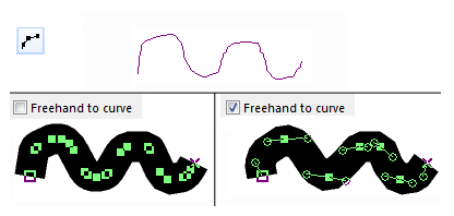
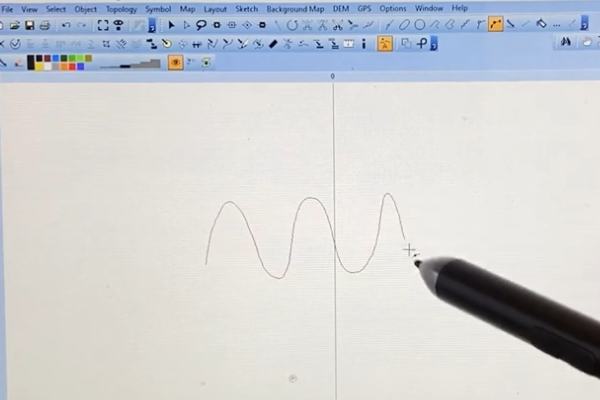
Freehand mode: Adapted for tablet with pen
If you work with tablet and a pen, using the Frehand mode will be much more confortable with this option as you can draw objects like intended.
Without this option, you would need to lift your pen some milimeters over your tablet when drawing an object.
See video here a video on YouTube.
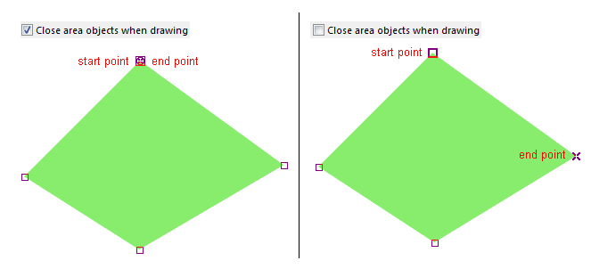
Close Area Objects
OCAD closes drawn area objects automatically if this option is checked. That means, if the start and end point of the object are different, OCAD adds an end point with the same position as the start point.
Choose Close Area Objects in the Topology part of the Object menu to close already drawn area objects.
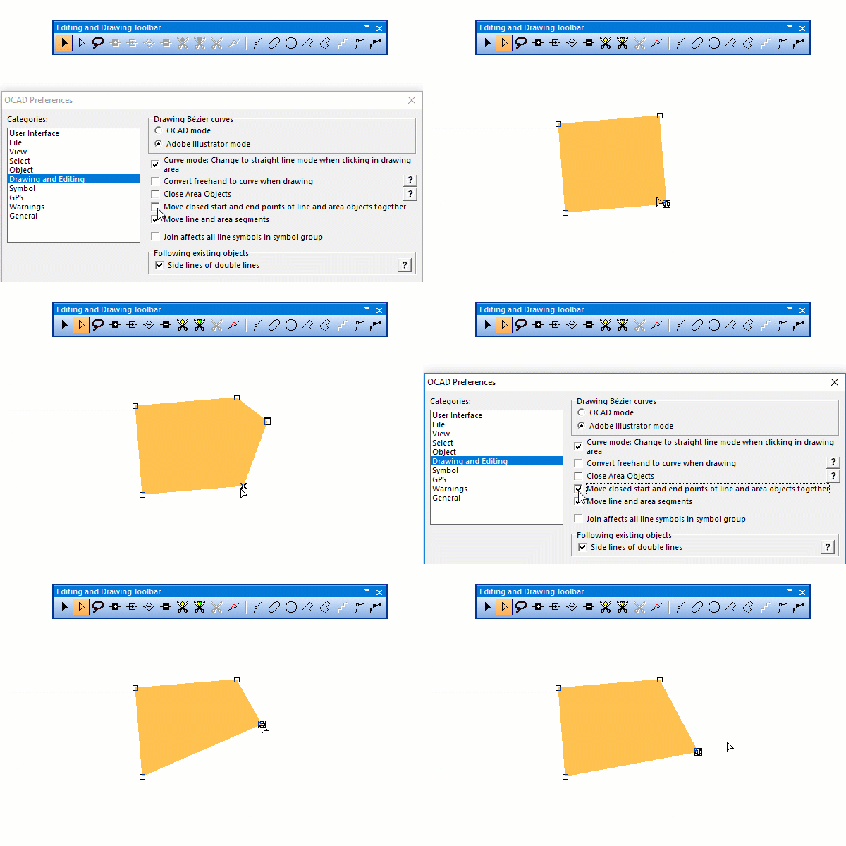
Move closed start and end points of line and area objects together
When this option is switched on, and the start and end points of a line or area object coincide (the line is closed), they are moved together during editing. If you move the start point, then the end point will also move.
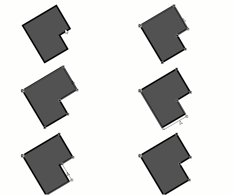
Move line and area segments
Activate this option to be able to move line and area segments.
Join affects all line symbols in symbol group
When this option is switched on, OCAD joins the ends of selected line objects that are in the same symbol group (symbol tree). If deactivated, OCAD only joins if the line objects have the same symbol.
The option affects the Join function and
Automatic Joining during drawing.
Following existing objects
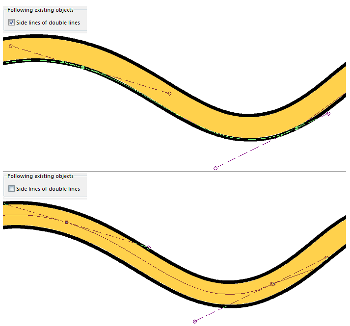
Uncheck the Side lines of double lines option if side lines of double lines should not be traced when you are following existing lines. You can find more about this topic on the Following Existing Objects page.
Tolerances
- Select objects: This tolerance defines the maximum distance on each side of a thin line where you can click to select it. Objects with a thicker main line than the tolerance level can be selected by clicking on the entire line width. The default value is 5 pixels.
 This tolerance is further used in multiple tools like Cut lines, Cut areas, Following existing objects, Reshape, Add Vertex, Remove Vertex, Change Vertex Type.
- Snapping: If you activate the Snapping tool, moving a vertex close to an objects has a snapping effect. This tolerance defines the maximum distance you have to approach to the object, so that the vertex snaps to it. The default value is 5 pixels.
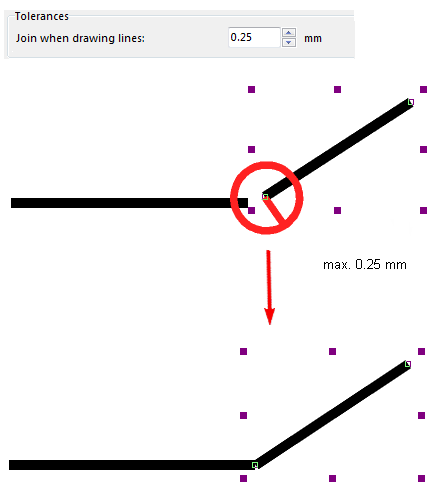
- Join when drawing lines: This tolerance defines the maximum distance a vertex has to approach to another line end to join it. The default value is 0.25 mm. If the line width is bigger than this tolerance then OCAD takes the line width as the tolerance. This tolerance is used for lines and areas
- Merge lines: This tolerance defines the maximum distance two line endes can be apart to still get merged.
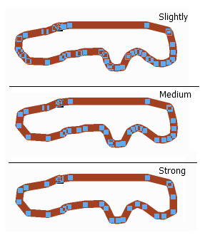
- Smooth when drawing freehand: There are three smoothing levels for freehand drawing mode: slightly, medium and strong. They correspond to 0, 1 and 2 in earlier OCAD versions.
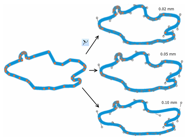
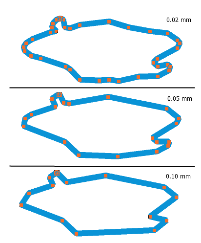
- Change to Bezier curve: This tolerance defines the maximum distance the vertices can move away from the original position by changing from polyline to Bezier curve. The default value is 0.10 mm. Note that the distance between the curve and the polyline can be greater between the vertices.
- Smooth (generalization): This tolerance is used by the Douglas-Peucker smoothing algorithm. Vertices that are closer to the direct line between the previous and the next vertex are removed. The default value is 0.05 mm.
This smooth tolerance is also used in the 'Change to Polyline' function.
Cursor color
You can change the cursor color to black, red, blue, purple or yellow by selecting a color in the dropdown list.
Scale Cursor Size
Check this option to enlarge the cursor to the default size on high-DPI monitors with Windows 10 Creators Update.
Mark
Set the mark size to normal, large or very large.
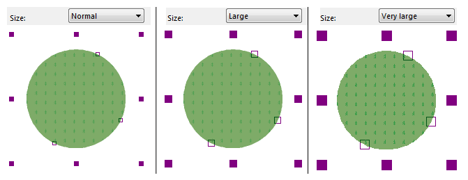
Choose a mark color by clicking the Setup icon.
The mark color is used during drawing and to mark the selected objects.
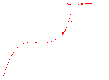
The GPS cursor in GPS Real Time mode is also drawn with the choosen mark color.
![]() OCAD uses the choosen mark color only on white background. Otherwise OCAD choose a color with high contrast to the background color.
OCAD uses the choosen mark color only on white background. Otherwise OCAD choose a color with high contrast to the background color.
Legibility
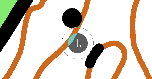
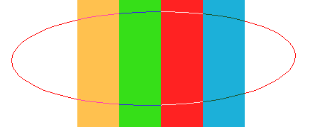
Show legibility halo: The legibility halo shall support the cartographer to draw objects with enough distance to each other.
The distance of this legibility halo is based on the IOF specifications for orienteering maps. The distance can also be defined by the user.
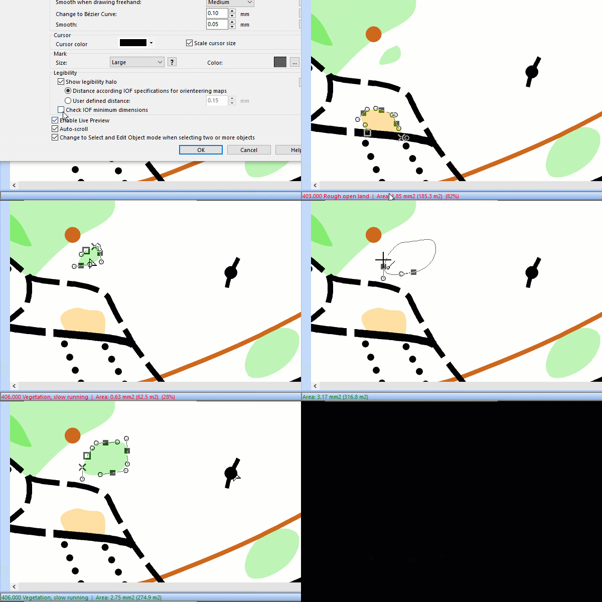
Check IOF minimum dimensions: Activate this option to check directly during drawing whether the drawn line or area object corresponds to the minimum dimension of the IOF specifications for orienteering maps.
In the lower left corner of the screen, an indication appears whether the object has already fulfilled the minimum dimension or not. If this is the case, the indication appears green. If not, the indication appears red. In this case, an additional percentage indication shows by how much the object is too small.
Enable live preview
Enable this option to show the real dimension of objects during drawing.
The preview of the objects will be shown in the Mark Color.
Auto scroll
Check this option if the map view should automatically scroll if you drag out of the drawing area. Disable Auto scroll if you have a slow PC.
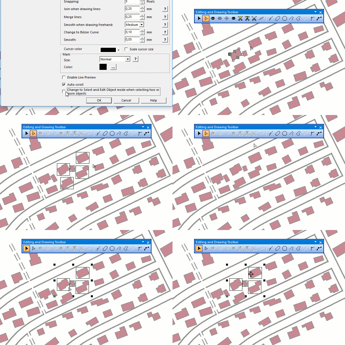
Change to Select and Edit Object mode when selecting two or more objects
Check this option to automatically get the Select and Edit Object mode when selecting two or more objects.
Symbol
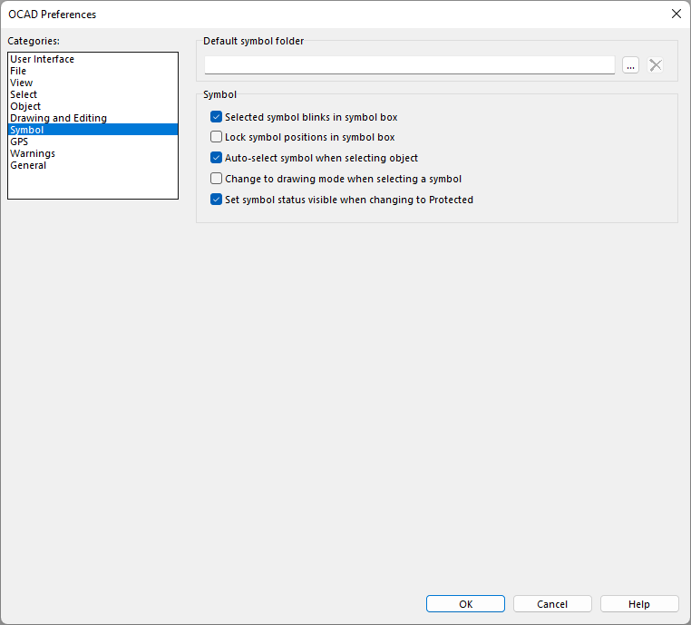
Default symbol folder
You can change the default symbol folder by clicking on the Browse icon. Choose a folder as default symbol folder which you want to load symbols from when you create a new map. Click on the
Delete icon to clear the current folder path. If no folder is selected, OCAD loads symbols from the Symbol folder in the OCAD program directory (usually: C:\Program Files\OCAD\OCAD 20xx\Symbol\) when you want to create a new map.
Symbol
- Selected symbol blinks in symbol box: If you check this option, the selected symbol blinks in the symbol box. This makes it easier to recognize the selected symbol.
- Lock symbol positions in symbol box: If you check this option, you are not able to drag and drop a symbol to a new position in the symbol box.
- Auto select symbol when selecting object: If you check this option, the corresponding symbol is automatically selected when you select an object. This does not work when you select multiple objects.
- Change to drawing mode when selecting a symbol: If you check this option, OCAD change to a drawing mode when selecting a symbol in the symbol box. If the symbol has a preffered drawing mode then OCAD change to this drawing mode.
- Set symbol status visible when changing to Protected: Check this option if you prefer to have the same behaviour as in earlier OCAD versions. In this case OCAD always sets the symbol status Visible when changing to Protected.
GPS
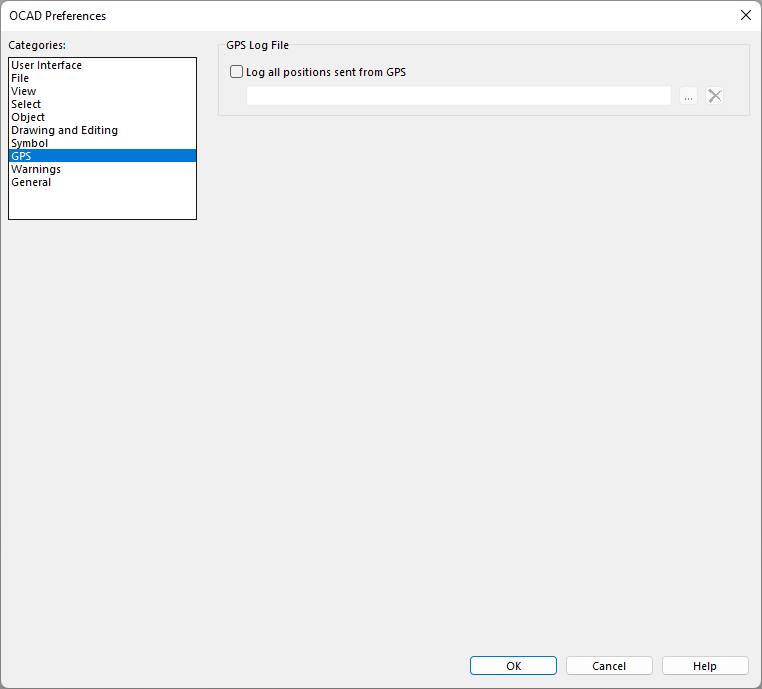
GPS Log File
Check the Log all positions sent from gps option to save all position sent from a GPS device in real time to a log file (Text-File). Click the Browse icon to choose a folder, the log files are saved to. The log files are named with the date and time the real time GPS is enabled.
Warnings
These warnings can be activated when you either print, export or import a map. If you check those options, you will get a warning message if you have hidden symbols on the map and you are trying to carry out one of mentioned operations.
Moving warnings
Enable the Move multiple objects option to get a warning message when you move multiple objects. Use this option in order to guard against moving multiple objects accidentally.
Database warnings
Check these options to show Database Compatibility warnings about 32/64bit and dBase.
General
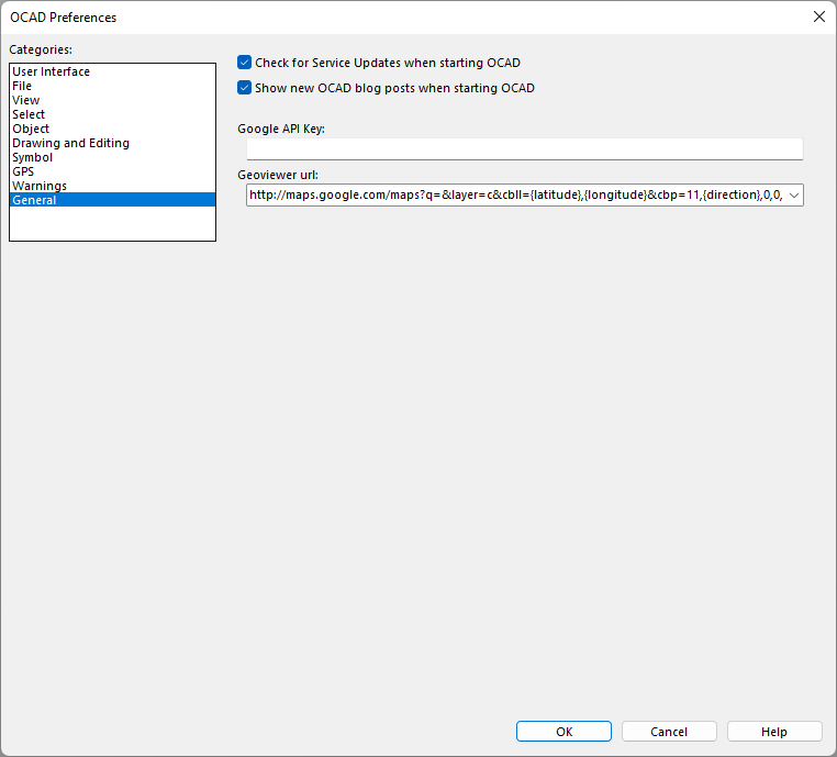
Updater
Disable the option Check for Service Updates when you start OCAD to not check for new free Service Updates when you start OCAD. Is some cases this check takes too long.
Known bugs are corrected in Service Updates. Additionally, new functions are added constantly with the subscription model. Therefore, we recommend using OCAD software always with the most recent Service Update to benefit from the quality improvements. The latest Service Update is also available on our website in the Download section.
OCAD Blog
If this option is activated, new OCAD blog posts are shown when you start OCAD.
Google API Key
Enter here your Google API Key. This key is used in the New Map Wizard to create a DEM via the Google Maps API.
Link: Get API Key
Geoviewer url
Enter here the user-defined url to open a geoviewer clicking the Open Geoviewer icon in the toolbar.
By default it is Google Street View.
Supported variables:
- {easting}
- {northing}
- {latitude}
- {longitude}
- {direction}
Examples:
- Google Street View: http://maps.google.com/maps?q=&layer=c&cbll={latitude},{longitude}&cbp=11,{direction},0,0,0
- Ordnance Survey map: https://osmaps.ordnancesurvey.co.uk/{latitude},{longitude},17
