Create a New Rectangle Symbol: Difference between revisions
No edit summary |
(→Grid) |
||
| (7 intermediate revisions by 3 users not shown) | |||
| Line 1: | Line 1: | ||
[[File:RectangleSymbols.PNG]] | [[File:RectangleSymbols.PNG]] | ||
[[File:Pro40px.PNG|This function is available in OCAD | [[File:Pro40px.PNG|This function is available in OCAD Professional.|link=https://www.ocad.com/en/products/ocad-for-cartography]][[File:Std40px.PNG|This function is available in OCAD Orienteering.|link=https://www.ocad.com/en/products/ocad-for-orienteering]][[File:Sta40px.PNG|This function is available in OCAD Starter.|link=https://www.ocad.com/en/products/ocad-for-orienteering]][[File:CS40px.PNG|This function is available in OCAD Course Setting.|link=https://www.ocad.com/en/products/ocad-for-orienteering]][[Category:Symbol]][[Category:Create a New Symbol]] | ||
You can create rectangle symbols with OCAD. | You can create rectangle symbols with OCAD. | ||
| Line 34: | Line 34: | ||
[[File:CornerRadius.PNG]] | [[File:CornerRadius.PNG]] | ||
===Line Style=== | |||
[[File:RectangleSymbolWithLineStyle.PNG]] | |||
The '''Line Style''' option is only available, if the '''Corner Radius''' is set to 0. In this case you can choose between the three common line styles to define the appearance of corners and line ends. | |||
[[File:Rectangle_LineStyle.PNG|400px]] | |||
===Drawing Mode=== | ===Drawing Mode=== | ||
* '''Horizontal rectangle:''' Activate this option if you want to draw only horizontal rectangles. | * '''Horizontal rectangle:''' Activate this option if you want to draw only horizontal rectangles. | ||
* '''Rotated rectangle:''' Activate this option if you want to draw rotated rectangles. | * '''Rotated rectangle:''' Activate this option if you want to draw rotated rectangles. | ||
===Grid=== | ===Grid=== | ||
The grid linie width is not alterable. So this option is obsolete. | |||
* '''On:''' Activate this field if you want to add a grid into the rectangle. | * '''On:''' Activate this field if you want to add a grid into the rectangle. | ||
* '''Cell width / Cell height:''' Enter the desired width and height for the cells. | * '''Cell width / Cell height:''' Enter the desired width and height for the cells. | ||
[[File:Hint.jpg|hint]] The effective cell width and cell height are always a divider of the drawn rectangle's total size.<br> | |||
[[File:RectangleGrid.PNG]] | [[File:RectangleGrid.PNG]] | ||
Latest revision as of 17:15, 15 September 2016
You can create rectangle symbols with OCAD.
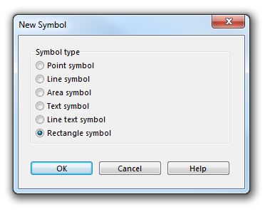
Choose the New command in the Symbol menu. Then, choose the Rectangle Symbol option in the New Symbol dialog to create a new rectangle symbol.
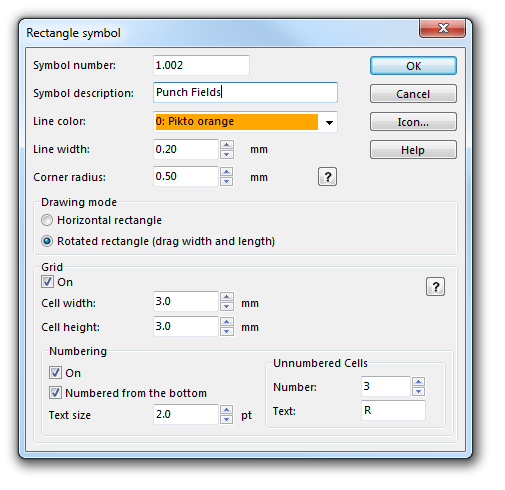
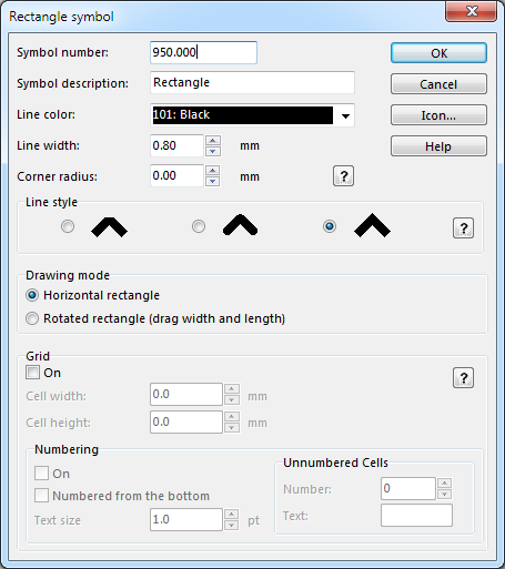
The Rectangle Symbol dialog appears.
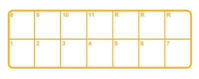
Rectangle symbols are used to draw rectangular frames (around the entire map or around parts of the map). A special use for Rectangle symbols are punch boxes for orienteering maps.
Symbol Number
Type a symbol number between 0.001 and 999999.999 in this field.
Symbol Description
Enter a symbol description in this field (e.g. Punch Box).
Line Color
Choose the color for the frame. All colors from the Color Table are listed in the dropdown list.
Line Width
Enter a line width for the frame.
Corner Radius
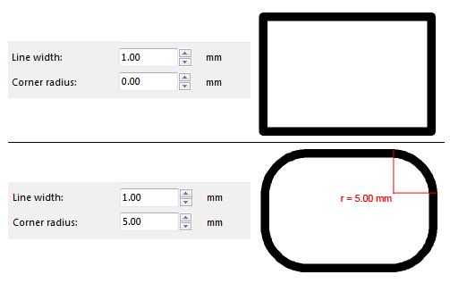
If you want the frame to have round corners, enter the corner radius here (measured to the center of the line), otherwise enter 0 here.
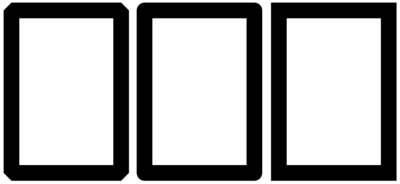
Line Style
The Line Style option is only available, if the Corner Radius is set to 0. In this case you can choose between the three common line styles to define the appearance of corners and line ends.
Drawing Mode
- Horizontal rectangle: Activate this option if you want to draw only horizontal rectangles.
- Rotated rectangle: Activate this option if you want to draw rotated rectangles.
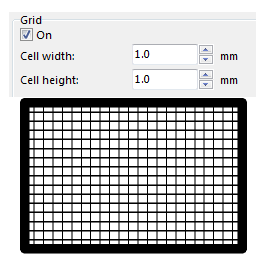
Grid
The grid linie width is not alterable. So this option is obsolete.
- On: Activate this field if you want to add a grid into the rectangle.
- Cell width / Cell height: Enter the desired width and height for the cells.
![]() The effective cell width and cell height are always a divider of the drawn rectangle's total size.
The effective cell width and cell height are always a divider of the drawn rectangle's total size.
Numbering
On
Activate this field if you want to add numbers to the grid.
Numbered from the Bottom
Normally, the cells are numbered starting from the top row. Check this box to start numbering from the bottom row.
Text Size
Choose the size in points for the text.
Unnumbered Cells
- Number: Enter here the number of cells used as reserved fields, if you want to create punch boxes. If you want all cells numbered enter here 0.
- Text: Enter here up to 3 characters which appear instead of the number in the reserved fields.
Icon
Click the Icon button in the dialog to create an icon for the symbol. The Icon Editor appears. Read more about this editor in the Icon Editor article.
Back to the Create a New Symbol page.
