Farben
Farben 


Diese Funktion ist nur eingeschränkt verfügbar im OCAD Viewer
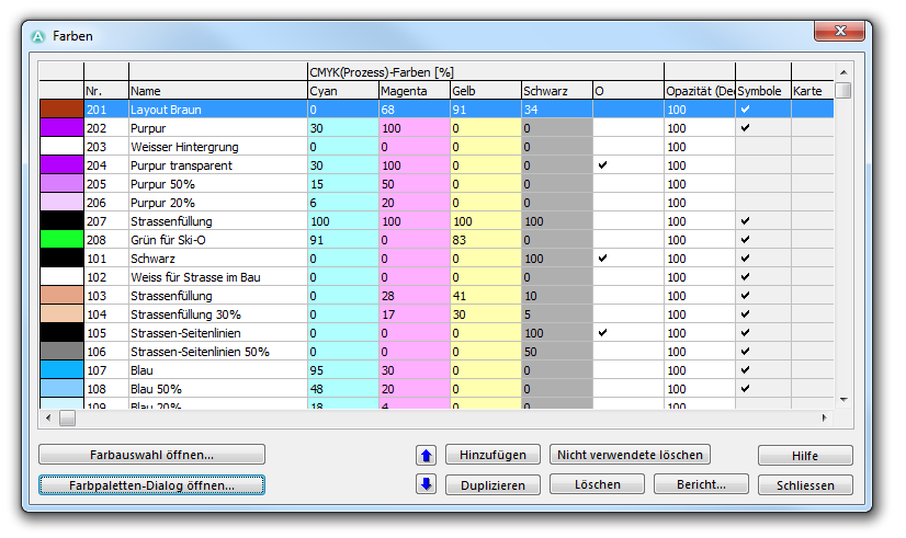
Wählen Sie diesen Menüpunkt im Karte-Menü, um die Farben und Echtfarben der Karte zu definieren. Der Farben-Dialog wird angezeigt. In diesem Dialog werden alle Farben, die Sie für die Karte verwenden können, aufgelistet. Hier können diese auch bearbeitet, neu erstellt oder gelöscht werden.
Die Farben werden auf dem Bildschirm und vom Drucker von unten aus gerendert. Die Farbe zuunterst in der Tabelle wird zuerst gerendert und die Farbe zuoberst als letztes. Deshalb wird ein Objekt A, mit einer Farbe unter deren eines Objekt B, auf der Karte unterhalb des Objekt B angezeigt.
Die Tabelle beinhaltet 18 Spalten:
Nummer und Name
Die erste Spalte gibt Ihnen eine Vorschau der Farbe, welche Sie in der gleichen Reihe definiert haben. Die zweite und dritte Spalte sind folgendermassen definiert:
- Nr.: In dieser Spalte wird die Farbnummer angezeigt. Jede Farbe muss eine Nummer zwischen 0 und 32000 haben. Die Nummer kann geändert werden, indem Sie auf diese klicken.
- Name: In dieser Spalte muss der Farbe einen Namen gegeben werden, welcher höchstens 45 Zeichen beinhalten darf. Dieser Name kann geändert werden, indem Sie auf diesen klicken.
CMYK (Prozess)-Farben
Die CMYK (Cyan, Magenta, Yellow, Key (Schwarz))-Werte der Farbe werden in diesen vier Spalten angezeigt. Diese Werte können durch deren anklicken geändert werden. Die Farbvorschau in der ersten Spalte wird sofort aktualisiert.
Overprint
In der O-Spalte können Sie die Overprint-Option an- oder ausschalten. Wenn die Overprint-Option aktiviert ist, werden die CMYK-Separationen nicht ausgespart (das heisst die CMYK-Separationen werden über der Farbe mit aktiviertem Overprint gedruckt/gerendert). Dies führt dazu, dass die Farbe dunkler erscheint, wenn diese auf einer anderen Farbe gedruckt wird. Das folgende Beispiel soll dies verdeutlichen.
In der Abbildung links ist das Overprint für die braune und schwarze Farbe aktiviert. Auf der rechten Seite hingegen ist diese Option bei diesen Farben deaktiviert. Sie können nun sehen, dass die braune Höhenkurve dunkler in der grünen Fläche erscheint. Ausserdem gibt es einen ähnlichen Effekt, wenn der schwarze Pfad die Höhenkurve kreuzt.
Man kann aber auch sehen, dass die Höhenkurve auf der gelben Fläche nicht dunkler erscheint. Dies entsteht aufgrund des Cyan-Wertes der braunen und gelben Farbe, welcher bei beiden Farben null ist. Overprint zeigt demnach bloss einen Effekt, wenn die obere Farbe mindestens einen CMYK-Wert null hat und gleichzeitig dieser Wert grösser wie null bei der zweiten Farbe ist.
In OCAD wird der Overprint-Effekt nicht gezeigt. Die Overprint-Funktion beeinflusst nur Farb-AI, EPS und PDF-Dateien wie auch CMYK-Separationen. Die Overprint-Funktion wird auch von einigen PostScript-Druckern unterstützt.
Opacity
In this column the opacity of the color in percentage can be entered by clicking the value.
An opacity value of 0 means that the color is not visible.
An opacity value from 1 to 99 means that the color is transparent with the corresponding intensity.
An opacity value of 100 means that the color is opaque.
Usage
If the Symbol column is checked, the color is used in at least one symbol.
If the Map column is checked, the color is used in at least one map object, including Image and Graphic Objects.
Spot Colors
Spot colors are used if the map is printed with PMS (Pantone) colors. If the map is printed with 4 colors (CMYK), spot colors needn't be defined.
You can define a spot color value for each color. Click in the corresponding field and enter a value in percentage.
- A value of 100 means that the color appears black on the separation.
- A value of 0 means that the color appears white on the separation and erases any black color.
- An empty field means that the color has no effect on the separation.
![]() The colors are rendered on the separation from the bottom up. The lowest color in the list is drawn first and the color on top of the list is drawn last. Therefore if you put 0 in one row, only colors below this row are erased.
The colors are rendered on the separation from the bottom up. The lowest color in the list is drawn first and the color on top of the list is drawn last. Therefore if you put 0 in one row, only colors below this row are erased.
![]() Putting a 0 is especially important for streets in order to enable automatic cleaning up of crossings. The color of the street infill must be above the color of the street sidelines. And in the row of the infill there must be a 0 for the spot color of the sidelines.
Putting a 0 is especially important for streets in order to enable automatic cleaning up of crossings. The color of the street infill must be above the color of the street sidelines. And in the row of the infill there must be a 0 for the spot color of the sidelines.
To create, edit and delete spot colors choose the Define Spot Colors item in the Map menu.
Functions
- Move Up: Click the Move Up icon to move the selected color one row upwards in the color table.
- Move Down: Click the Move Down icon to move the selected color one row downwards in the color table.
- Add: Click this button to add a new color.
- Duplicate: Click this button to duplicate the selected color. The duplicated color is inserted below the selected color.
- Delete unused: Click this button to delete all colors that are neither used in any symbol nor any map object.
- Delete: Click this button to delete the selected color.
- Report: Click this button to save a report of the colors as a Word, Excel, Html or Text file. Open the report with the Open Recently Exported Documents command from the File menu.
- Choose color from Color Picker: Click this button to edit the selected color with the Color Picker.
- Open color swatch dialog: Click this button to compare the colors from the current open OCAD file with a color swatch from a reference file.
![]() If you have a map with a lot of objects, it may take some seconds until the Color dialog appears. OCAD is checking through all objects to find all colors used in the symbols and in the map. If you want OCAD to display the Colors dialog immediately, press the Shift key when choosing Colors in the Map menu. OCAD opens the dialog instantly and hides the Symbol and Map columns as well as the Delete unused button. This dialog looks as follows:
If you have a map with a lot of objects, it may take some seconds until the Color dialog appears. OCAD is checking through all objects to find all colors used in the symbols and in the map. If you want OCAD to display the Colors dialog immediately, press the Shift key when choosing Colors in the Map menu. OCAD opens the dialog instantly and hides the Symbol and Map columns as well as the Delete unused button. This dialog looks as follows:
Load Colors From 


Choose this command in the Map menu to load a color table from a different OCAD-File. The Load Colors From dialog box is displayed. Choose a map file which the color table shall be loaded from. Click the Open button to continue. Another Load Colors From dialog box appears. You have two options:
- Replace existing colors: Choose this option to overwrite the existing color table of the current map with the new one.
- Add to existing colors: Choose this option to add the new colors to the existing color table.
Click the OK button to finish.
Load Colors and Symbols From 


Choose this command in the Map menu to load a symbol set from a different OCAD-File. The Load Colors and Symbols From dialog box is displayed. Choose a map file which the symbol set shall be loaded from. Click the Open button to continue. Another Load Colors and Symbols From dialog box appears. You have two options:
- Replace existing colors and symbols: Choose this option to overwrite the existing symbol set and color table of the current map with the new ones.
- Add to existing colors and symbols: Choose this option to add the new symbols and colors to the existing color table.
You have the option to use a CRT-File to import the symbol set. In the first column of the cross reference table the symbol numbers of the current map are listed. In the second column symbol numbers of the other OCAD-File are listed, namely those numbers of symbols, which the current symbol has to be replaced with. As an example, a CRT row which is defined as 526.000 813.001, means that the symbols of all objects with the symbol number 526.000 will get the symbol of the other OCAD-File with the number 813.001.
Visit the Cross Reference Table page to get detailed information about using CRT-Files. Click the Load button to load a CRT-File.
Click the OK button to finish.
![]() The error message "Cannot import symbol" appears if OCAD was not able to load a symbol. The Load Colors and Symbols From process is aborted.
The error message "Cannot import symbol" appears if OCAD was not able to load a symbol. The Load Colors and Symbols From process is aborted.
Previous Chapter: Create a New Map
Next Chapter: Create a New Symbol
Back to Main Page
To the Map page.


