Topology
Join 


Choose the ![]() Join function in the Topology menu or in the Edit Functions Toolbar.
This function is active if a line object is selected.
Join function in the Topology menu or in the Edit Functions Toolbar.
This function is active if a line object is selected.
Use this function to adjust adjoining line ends so that they coincide. Only line objects with the same symbol are joined. This is especially useful when continuing a line object such as a contour. Note that the objects remain independent objects, but the coordinates of the end vertices are equalized. If you want to merge objects, choose the Merge command.
Automatic Joining
If you enable ![]() Automatic Joining in the Edit Functions Toolbar, end points of lines or areas are joined automatically when finishing drawing a line or area near another end. The Join when drawing lines tolerance can be set in the Drawing and Editing category of the OCAD Preferences. To switch off the automatic joining temporary during drawing, press the Shift key when terminating the line or area object.
Automatic Joining in the Edit Functions Toolbar, end points of lines or areas are joined automatically when finishing drawing a line or area near another end. The Join when drawing lines tolerance can be set in the Drawing and Editing category of the OCAD Preferences. To switch off the automatic joining temporary during drawing, press the Shift key when terminating the line or area object.
Tolerance Value
Define how close two line end points have to be for joining them in the Drawing and Editing category of OCAD Preferences.
Smooth
Visit the Smooth page to find some information about the ![]() Smooth function.
Smooth function.
Generalize Buildings
Allows to simplify the building geometry or rectangle it.
- Click on Generalize Buildings in the Topology menu. The Generalize Buildings dialog opens.
- Choose between Geometry simplification and Rectangle option.
- Geometry simplification:
- Define the angle change and the segment offset as thresholds if vertices should be deleted.
- There are also options to keep Corner vertices and Dash vertices.
- Define the angle change and the segment offset as thresholds if vertices should be deleted.
- Rectangle:
- Decide if each selected object will be replaced a rectangle, if all selected objects will be replaced with one rectangle or if the selected object will be replaced with a series of rectangles. Enter the Number of rectangles if you choose the last option.
- Enter a factor to scale the total area.
 The result of replacing three buildings with one rectangle may is better if the new area is more than 100% of the sum of the three areas because of the space between the original buildings. In such cases often a factor of 130-140% is used.
- Decide if each selected object will be replaced a rectangle, if all selected objects will be replaced with one rectangle or if the selected object will be replaced with a series of rectangles. Enter the Number of rectangles if you choose the last option.
- Geometry simplification:
- Click OK

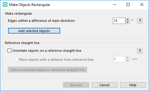
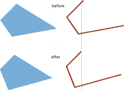
Make Objects Rectangular
This function allows to rectify line and area objects. Angles close to 90° are forced to be exactly 90°.
- Select the object(s) that should be rectified.
- Click on Make Objects Rectangular... in the Topology menu to open the non-modal Make Objects Rectangular dialog.
- Define the allowed angle tolerance as a difference from 90°. A tolerance of 10° means that all edges with an angle change between 80 and 100° will be rectified.
- Click on Add selected objects. This is necessary since this is a non-modal dialog.
- Decide, if the selected objects shall also be orientated along a reference line.
- Define the distance between the object(s) and the reference line.
- Select the reference line object on the map and click Choose selected object as reference straight line
- Click Execute button to execute the function.


Close Area Objects
Choose this function from the Topology menu.
This function closes the desired area(s).
- Select the area objects to close either in the drawing area or in the symbol box. Do not select any area object if you want to close all area objects on the map.
- Choose the Close Area Objects command.
- The Close Area Objects dialog appears.
- Choose wheter you want to close all area objects, all area objects from the selected symbols or all selected are objects on the map.
- Click the OK button to finish. OCAD closes the desired areas (which means that the end and start point of an area object have the same coordinate).
![]() OCAD is able to close area objects automatically when drawing. Enable the Close area objects when drawing option in the Drawing and Editing category of OCAD Preferences to activate this function.
OCAD is able to close area objects automatically when drawing. Enable the Close area objects when drawing option in the Drawing and Editing category of OCAD Preferences to activate this function.
Direct Area Object CCW
Choose this function from the Topology menu.

This function change the direction of area object that choose objects have counterclockwise (CCW) direction. In some cases that is necessary. For example for area objects with border line.
The direction of an area object can be change with the Reverse Object Direction function.
Lengthen Line Text Objects
Choose this function from the Topology menu.
The function lengthens the selected line text objects by distance or a percent value of current length. The lenghtening is always added at the end of the line text object. Choose the option Lengthen by distance or Lengthen by percent of current length and enter the distance in mm or the percent value.

Remove Undershoots and Overshoots
Choose this function from the Topology menu.
This function removes over- and undershoots of the selected lines.
This command is enabled when line objects are selected.

- Select the line objects with over- and/or undershoots.
- Choose the Remove Overshoots and Undershoots function.
- The Remove Overshoots and Undershoots dialog box appears.
- Decide wheter you want to remove overshoots, undershoots or both of them.
- Define a tolerance value. This value determines how much a line must over- or undershoot so that it gets cut or extended.
- Click the OK button to finish.
![]() If you want to prevent from creating under- and overshoots, enable the Snapping function.
If you want to prevent from creating under- and overshoots, enable the Snapping function.
Insert, Cut or Add at Intersections
You can find this function in the Topology menu.

- Select the line objects you want to work with. Please note that the function applies only to intersections and self-intersections of the seleteced objects.
- Choose the Insert, Cut or Add at Intersections function.
- The Insert, Cut or Add at Intersections dialog appears.
- Choose wheter you want to Insert vertex at intersections, to Cut line objects at intersections or to Add Point object at intersections.
- If you want a vertex at intersections, you have to choose between a Normal Vertex, a Corner Vertex or a Dash Vertex (Read more about vertices on the Vertices page).
- If you want a point object at intersections, you have to pick one.
- If desiresd, check the Include touching objects option.
- If this option is checked, touching objects get the same reaction as intersected objects.
- Click the OK button to finish.
This function can be useful if you want to improve the graphic appearance of dashed lines' intersections. For example, if you insert a Dash Vertex, the intersection will be in the middle of a dash (Learn more about vertices on the Vertices page).
Remove Duplicate Vertices from selected Objects
Choose the Remove Duplicate Vertices from selected Objects command in the Topology menu to remove the duplicate (=consecutive with identical coordinates) vertices of selected objects.
Back to Main Page
Previous Chapter: Edit Object
Next Chapter: Symbol