O-training with OCAD: Difference between revisions
No edit summary |
|||
| Line 56: | Line 56: | ||
== Multitechnique == | == Multitechnique == | ||
* Open your '''''[Map File]'''''. | * Open your '''''[Map File]'''''. | ||
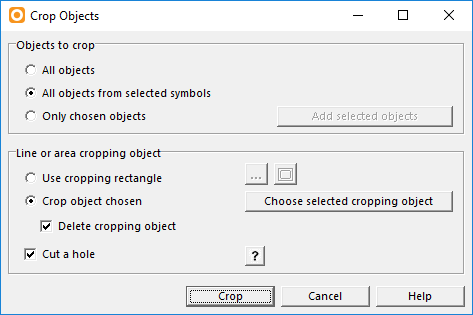
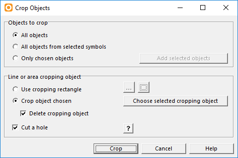
* Use the [[Crop_Objects|Crop]] funtion to differ which symbols you want to crop in which parts of your map. | * Use the '''[[Crop_Objects|Crop]]''' funtion to differ which symbols you want to crop in which parts of your map. | ||
[[File:Multitechnique1.PNG]] | [[File:Multitechnique1.PNG]] | ||
Revision as of 16:55, 22 May 2018
Learn how to make o-technical excercises.
Preparation
For a course setting project, you need two OCAD files:
- A [Course Setting File]
Like map files it has the extension .ocd, but it has a special internal mark to identify it as a course setting file.
- A [Map File]
This is your OCAD map which will be loaded as Background map for the Course Setting Project.
![]() You can also load a raster image (PNG, JPG, ...) as background map. However, not all trainings described on this page will work if you don't have an OCAD Map File.
You can also load a raster image (PNG, JPG, ...) as background map. However, not all trainings described on this page will work if you don't have an OCAD Map File.
Now start a New Coure Setting Project. Make sure the map scale of your Course Setting file is the same as your Map file.
Simple Course
See this Video about Course Setting Basics. More is coming soon...
Corridor
- Open your [Course Setting File].
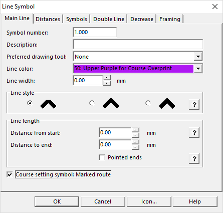
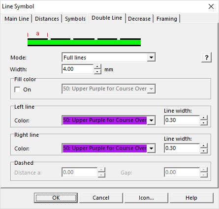
- Choose New in the Symbol Menu and create a new Line Symbol.
- - In the Mail Line tab, activate Course setting symbol: Marked route.
- - In the Double Line tab, choose the desired width of the corridor (e.g. 4mm) and the border lines.
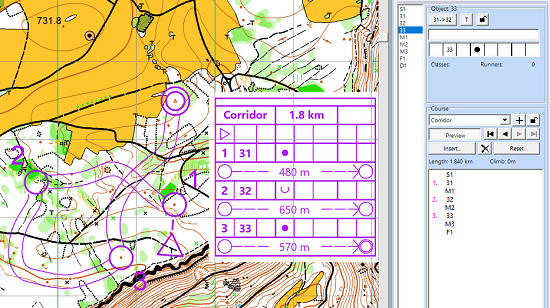
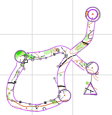
- Draw your corridor. Each corridor will appear as a Mared Route in the Course Setting Box. Insert the corridors in your course.
- Edit your corridor in a next step.
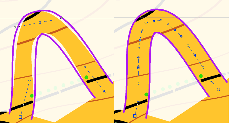
- - Cut overlapping parts.
- - Insert additional vertices in sharp turns.
- Cover the remaining parts with white
- - Use the White background (Symbol 760) and the Follow existing objects
- - Activate Follow existing objects under Options> OCAD Preferences> Drawin and Editing to enable line following for double lines (hold the Ctrl button).
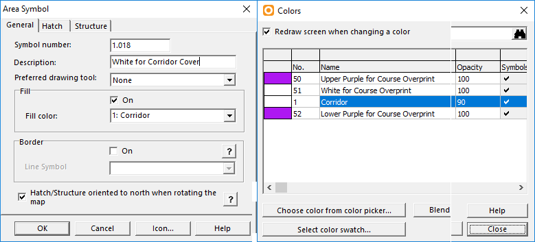
- - Instead of using White background for covering, first define a new white color (Map>Colors>Add) and then create a new area symbol (Symbol>New>Area Symbol) where you use this color as Fill Color. Like this you can set the Opacity of the white color to e.g. 90%, so you are not completly lost when leaving the corridor.
Reduce Map
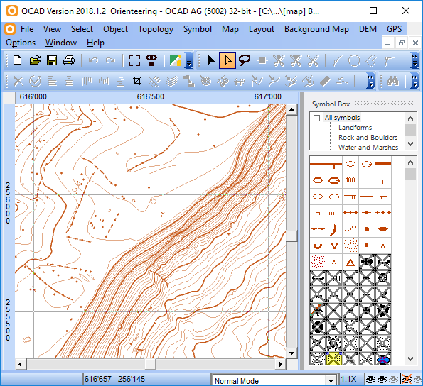
- Open your [Map File].
- Select the symbols you want to hide in the Symbol Box and go to Symbol>Hide Object or simply press F4.
- Save the map, load it as background map in your [Course Setting File] and set courses.
Multitechnique
- Open your [Map File].
- Use the Crop funtion to differ which symbols you want to crop in which parts of your map.
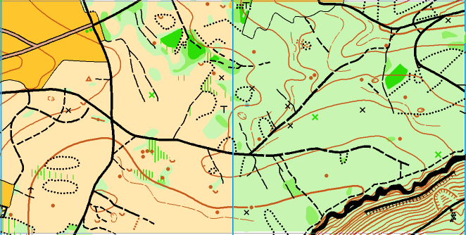
In the following example, we used the yellow and green areas as Crop Objects. In the yellow part, all paths and roads were cropped. In the green area, all terrain objects. You can use the Crop funktion as often as you like in the same [Map File].
- Save the map, load it as background map in your [Course Setting File] and set courses.
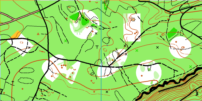
Island O
- Open your [Map File].
- Draw an area object over your map and Cut Holes in it.
- Use the Crop function to crop everything except the holes.
- Save the map, load it as background map in your [Course Setting File] and set courses.
