Example Geological Line Symbol
Jump to navigation
Jump to search
To create this symbol start from an empty line symbol and then do the following steps:
In the Distances page:
- Enter the maximum distance between the red dots (from center to center) as Main length a.
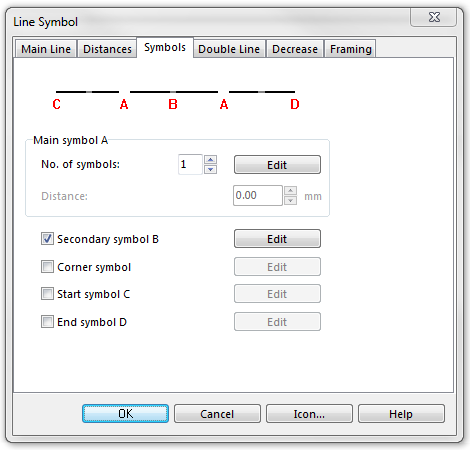
In the Symbols page:
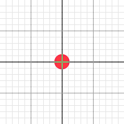
- In the box Main symbol A click Edit to go to the symbol editor. There you draw the desired red dot (at the coordinates 0, 0).
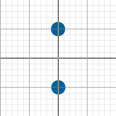
- In the line Secondary symbol B click Edit to go to the symbol editor. There you draw the 2 blue dots, both on the y-axis (at the coordinates 0, d and 0, -d). Secondary symbol B will be automatically checked when returning from the symbol editor.
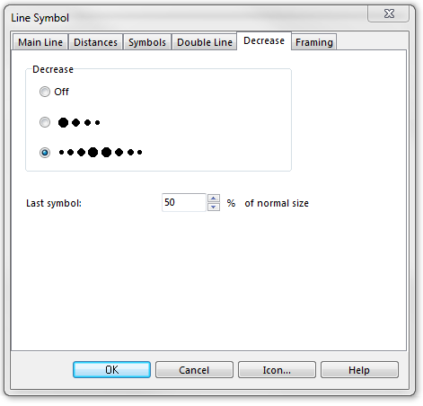
In the Decrease page:
- In the Decrease box select the last radio button (decreasing to both sides).
- For Last symbol enter the desired decreasing percentage (e.g. 50%).
Remark: When drawing objects with this symbol, you can influence the increasing/decreasing by setting dash vertices. If you set 2 dash vertices along the line, the dot size will increase until the first dash vertex, then remain on the maximum size until the second dash vertex and then decrease towards the end of the line.
Download link: Example_GeologicalLineSymbol.ocd
Back to Create a New Symbol


