Example Full Line: Difference between revisions
Jump to navigation
Jump to search
No edit summary |
No edit summary |
||
| (One intermediate revision by the same user not shown) | |||
| Line 1: | Line 1: | ||
[[File:FullLine.PNG]][[Category:Symbol]][[Category:Create a New Symbol]] | [[File:FullLine.PNG]][[Category:Symbol]][[Category:Create a New Symbol]] | ||
To create this line symbol, enter the following parameters to a | To create this line symbol, enter the following parameters to a newly created line symbol: | ||
'''Main Line''' | '''Main Line''' | ||
* Line color: black (define and edit colors in the '''[[Colors]]''' dialog, which can be found in the '''[[Map]]''' | * Line color: black (define and edit colors in the '''[[Colors]]''' dialog, which can be found in the '''[[Map]]''' menu) | ||
* Line width: 0.2 mm | * Line width: 0.2 mm | ||
| Line 13: | Line 13: | ||
---- | ---- | ||
Back to the '''[[Create a New Line Symbol]]''' | Back to the '''[[Create a New Line Symbol]]''' page. | ||
Latest revision as of 11:02, 31 January 2013
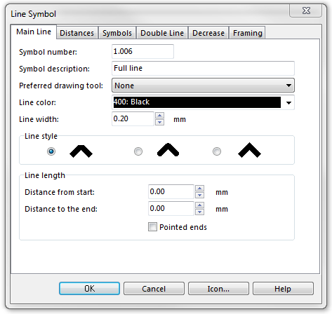
To create this line symbol, enter the following parameters to a newly created line symbol:
Main Line
- Line color: black (define and edit colors in the Colors dialog, which can be found in the Map menu)
- Line width: 0.2 mm
Download link: Example_FullLine.ocd
Back to the Create a New Line Symbol page.
