Drawing an Object: Difference between revisions
(/* Edit an Object File:Space.PNGThis function is available in OCAD Professional.|link=https://www.ocad.com/en/products/ocad-for-cartographyThis function is available in OCAD Orienteering.|link=https://www.ocad.com/en/products/ocad-for-orienteeringThis...) |
(/* Edit an Object File:Space.PNGThis function is available in OCAD Professional.|link=https://www.ocad.com/en/products/ocad-for-cartographyThis function is available in OCAD Orienteering.|link=https://www.ocad.com/en/products/ocad-for-orienteeringThis...) |
||
| Line 323: | Line 323: | ||
: [[File:Icon_FindSelectedObjects.PNG|find selected objects]] '''Find selected objects:''' | : [[File:Icon_FindSelectedObjects.PNG|find selected objects]] '''Find selected objects:''' | ||
:[[File:Find_Objects.gif|Find selected objects]] | :[[File:Find_Objects.gif|Find selected objects]] | ||
Display the selected objects in the center of the drawing window. | |||
: [[File:Icon_ChangeSymbolOfObject.PNG|change symbol of object]] '''Change symbol of object:''' Assign a new symbol to the selected object. | : [[File:Icon_ChangeSymbolOfObject.PNG|change symbol of object]] '''Change symbol of object:''' | ||
: [[File:Change_Symbol.gif|Change symbol of object]] | |||
Assign a new symbol to the selected object. | |||
: [[File:Icon_ChangeSymbolForAllObjectsWithThisSymbol.PNG|Change symbol of all objects with this symbol]] '''Change symbol of all objects with this symbol:''' Assign a new symbol to all objects with a specific symbol. | : [[File:Icon_ChangeSymbolForAllObjectsWithThisSymbol.PNG|Change symbol of all objects with this symbol]] '''Change symbol of all objects with this symbol:''' Assign a new symbol to all objects with a specific symbol. | ||
: [[File:Icon_Join.PNG|join]] '''Join:''' Join the ends of selected line objects that have the same symbol or the same symbol group. You can change this option in the [[OCAD_Preferences#Move_closed_start_and_end_points_of_line_and_area_objects_together|Preferences]]. | : [[File:Icon_Join.PNG|join]] '''Join:''' Join the ends of selected line objects that have the same symbol or the same symbol group. You can change this option in the [[OCAD_Preferences#Move_closed_start_and_end_points_of_line_and_area_objects_together|Preferences]]. | ||
Revision as of 09:28, 12 September 2016

Draw a Point Object 


- Choose a point symbol.
- Select any drawing mode. The cursor appears as a crosshair with a point in the lower right-hand corner.
- Click a position in the drawing window.
- The point object appears.
 -To define a specific direction of for the object, click and hold the left mouse button on desired position; then drag to the direction you wish the object to be oriented to.
- -The object can be adjusted retrospectively. To do this, select the point object and align it using the Indicate direction of area pattern, point or text object function.
 Drawing point objects
Draw a Line or Area Object
You must select one of the eight drawing modes to draw a line or area object.
- The cursor appears as a crosshair with the symbol for the selected drawing mode in the lower right-hand corner.
- In the lower left-hand corner will be shown the total line length.
![]() If you draw an area the finishing line is shown dashed, whilst the left mouse button is pressed.
If you draw an area the finishing line is shown dashed, whilst the left mouse button is pressed.
Draw a Straight Line

- To draw straight lines such as streets, power lines or sidewalks, select Straight line mode.
- Select a line or area symbol from the symbol box.
- Select Straight line mode.
- Position the cursor at the point where you want to start the line, then click and hold the left mouse button and drag the cursor in the desired direction. The help line provides a preview of the line that has just been drawn.
- To add a vertex to the straight line, release the left mouse button. Now press and hold the left mouse button once more and drag the cursor in the desired direction. Repeat this process as often as necessary.
- Click the left mouse button when you have finished drawing and the help line is transformed into the selected line or area symbol.
Draw a Curve

Select Bézier Curve mode to draw flowing or curved lines such as contours or shore lines. Drawing Bézier Curves requires some practice as you need to get a feeling for where the radius or curvature of a flowing or curved line changes. The turning point is where the vertex and its tangents need setting. Once you have mastered this technique, you will be able to draw curved lines and area objects efficiently and precisely.

- Select a line or area symbol from the symbol box.
- Select Bézier-Curve mode.
- Position the cursor at the point where you want to start the line, click and hold the left mouse button and drag the cursor to form the radius you want and release the left mouse button.
- Position the cursor at the next inflection, click and hold the left mouse button and drag the cursor to form the radius you want and release the left mouse button. The help line provides a preview of the curved line that has just been drawn. Repeat this process for each inflection point.
- Click the left mouse button when you have finished drawing and the help line is transformed into the selected line or area symbol.

- -If you are unhappy with the tangent, simply click the Backspace
 button. The last tangent will be deleted and you can try again. You can delete as many tangents as you like up to the beginning of the line. This is not possible once the object has been completed.
- -Sinuous lines can be managed easily by placing tangents at the outermost points.


- You can force a corner vertex by dragging two tangents from the same vertex point. Curve: Tangents 2 and 3 start at the same point but move in different directions. A corner vertex is created.

- Drawing curve object

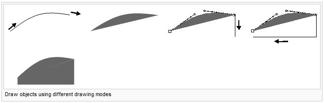
- You can draw parts of a line or area object using different drawing modes. Select the appropriate symbol and draw the first part of your object using a drawing mode. Now press the Tab button until the desired drawing mode appears and then continue drawing.

- You can lengthen existing line objects or expand area objects. Simply select the appropriate symbol, press and hold the Shift
 button and start drawing at the beginning or end of the existing object. Release the Shift button once the line or area has been added.
 - Continuing existing objects
- To draw horizontal or vertical lines, press and hold the Alt button. The Shift and Alt button functions can be combined.
- Download this excerice to draw Bézier curves.
Draw a Freehand Line

Freehand drawing mode plots the movement of the cursor and converts it into a line. Tracing flowing or curved lines using this mode is not very efficient or precise. Depending on the drawing speed and selected smoothing factor (1, 2 or 3), the line may appear somewhat angular because the vertices are connected using straight lines.
- Select a line or area symbol from the symbol box.
- Select Freehand mode.
- Position the cursor at the beginning of the line, press the left mouse button briefly and trace the line you want using the mouse.
- Click the left mouse button when you have finished drawing and the help line is transformed into the selected line or area symbol.
If you draw in freehand mode the same way as in straight mode, normal points will be placed at the corners. Unlike corner points, normal points do not affect dashed lines.
Draw a Rectangular Area

Select Rectangular mode if you want to draw rectangular areas or objects such as buildings or squares. This drawing mode creates a right-angle in every corner and ensures the start and end points of the outline are identical.
- Select a line or area symbol from the symbol box.
- Select Rectangular mode.
- Position the cursor on one of the corners of the longest side of the rectangular area. Press and hold the left mouse button and drag the cursor along the longest side to the next corner.
- When the cursor reaches the corner, release the left mouse button and then press it again. Hold the left mouse button and drag the cursor towards the next corner. The help line provides you with a preview of the straight line that has just been drawn. A broken line shows you what the rectangular object will look like when you have finished. Repeat the above process to draw a line to the third corner.
- Click the left mouse button to finish the drawing; the help line is then transformed into the selected line or area symbol.
You should always draw the longest side of a rectangular area first since it is easier to define the rectangular orientation of an area from the longer side.

Draw a Rectangular Line

Select Rectangular line mode if you want to draw rectangular line objects such as sidewalks or stairs. This drawing mode creates a right-angle in every corner. The only difference between Rectangular line mode and Rectangular mode is that the start and end points are not identical when using rectangular line mode.
- Select a line symbol from the symbol box.
- Select Rectangular line mode.
- Position the cursor at the beginning of the rectangular line. Press and hold the left mouse button and drag the cursor along the longest side to the next corner.
- When the cursor reaches the corner, release the left mouse button and then press it again. Hold the left mouse button and drag the cursor towards the next corner. The help line provides a preview of the line that has just been drawn. Repeat this process until you reach the end of the rectangular line.
- Click the left mouse button when you have finished drawing and the help line is then transformed into the selected line symbol.
You should always draw the longest side of a rectangular line first since it is easier to define the rectangular orientation of a line from the longer side.
Draw a Stairway

Select Stairway drawing mode if you want to draw a rectangular stairway.
- Select a line symbol from the symbol box.
- Select Stairway mode.
- Position the cursor at the beginning of the stairway. Press and hold the left mouse button and drag the cursor along the longest side to the next corner.
- When the cursor reaches the corner, release the left mouse button and then press it again. Hold the left mouse button and drag the cursor towards the next corner. The help line provides a preview of the line that has just been drawn.
- Hold the left mouse button and drag the cursor to the first step. The step help lines provide a preview of the stairway. Release the left mouse button.

Draw a Circular Object

Select Circle mode if you want to draw circular objects such as roundabouts or silos.
- Select a line or area symbol from the symbol box.
- Select Circle mode.
- Position the cursor at the edge of the object, then press and hold the left mouse button and drag the cursor to the opposite edge. Release the mouse button. The help line is transformed into the selected line or area symbol.
- -The outline or circular line is drawn as a Bézier curve.
- -You can also drag the circle from the center point. Simply press and hold the Shift button and drag a radius.
- -Clicking the center of the circle with the right mouse button without dragging displays the Draw Circle dialog box. Here you can enter the radius of the circle in mm or m.
- -You can also drag the circle from the center point. Simply press and hold the Shift
- Drawing circular objects
Draw an Elliptical Object

Select Ellipse mode if you want to draw oval objects such as hills or dips.
- Select a line or area symbol from the symbol box.
- Select Ellipse mode.
- Position the cursor at the beginning of the longer ellipse axis, then press and hold the left mouse button and drag the cursor towards the end of the axis.
- Position the cursor at the beginning of the shorter ellipse axis, then press and hold the left mouse button and drag the cursor towards the end of the axis. Release the mouse button. The help line is transformed into the selected line or area symbol.

- The outline or ellipse line is drawn as a Bézier curve.
- Drawing elliptical objects
Draw Multiple Point Objects

This drawing tool is used to draw several point objects that are placed on a line with a constant interval.
- Choose a point symbol in the symbol box.
- Choose the drawing tool Drawing multiple point objects from the Edit and Drawing toolbar.
- Draw a line from the position of the first to the position of the last feature.
- The Dialog Draw Multiple Point Objects appears:

Enter the number of objects and click the OK button.
The defined number of objects are drawn:
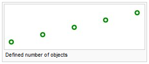
- If the number of objects is 1, the objects position will be in the center of the drawn line.

Laser Rangefinder Drawing Mode
Laser rangefinder drawing tool.
Numerical Drawing Mode

Select Numeric mode if you have measurement values or coordinate pairs for specific objects.
Construct a point object using distance or azimuth measurements.
- Select a point symbol from the symbol box.
- Select Numeric mode.
- Enter the coordinates of your location in the Easting and Northing fields. A small cross highlights the position in the drawing window.
- Enter the length in mm or m in the Length field and the Angle in a clockwise or counterclockwise direction.
- Click End.
- The angle and distance measurements are used to position the point object.
- -You can change the direction from clockwise to counterclockwise, or vice-versa, by clicking the Counterclockwise or Clockwise buttons.
- -You can change the unit of measurement from millimeter to meter, or vice-versa, by clicking the Millimeter or Meter button.
Construct a line or area object using coordinate pairs.
- Select a line or area symbol from the symbol box.
- Select Numeric mode.
- Enter the coordinates of your first coordinate pair in the Easting and Northing fields. A small gray cross highlights the position of the first coordinate pair in the drawing window.
- Select the construction mode
 Enter positions.
 - Enter the coordinates of the second coordinate pair in mm or m and click Next. A help line appears between the first and second coordinate pair. Repeat this process as often as necessary; the help line is extended each time. Click End once you have entered the final coordinate pair.
- The sections are then transformed into the selected line or area symbol.
Construct a line or area object using distance or azimuth measurements.
- Select a line or area symbol from the symbol box.
- Select Numeric mode.
- Enter the coordinates of your starting point in the Easting and Northing fields. A small cross highlights the position of the starting point in the drawing window
- Select the construction mode
 Enter length and angle.
 - Enter the length in mm or m in the Length field and enter the Angle in a clockwise or counterclockwise direction. A help line appears that displays the distance and azimuth from the starting point. Repeat this process as often as necessary; the help line is extended each time. Click End once you have entered the final distance and azimuth values.
- The sections are then transformed into the selected line or area symbol.
Place a Text Object
Text and line text symbols are available for placing text. Text symbols are generally aligned horizontally. Line text symbols follow the flow of rivers or streets.

Place a text object
You can choose text frames or anchor points for placing text objects.
Define a text frame
- Select a text symbol from the symbol box.
- Select a drawing mode.
- Position the cursor on the upper left-hand corner of the desired text frame, then click and hold the left mouse button and drag the cursor to the lower right-hand corner. Release the mouse button. The text cursor for inputting text appears.
- Enter the desired text. The line break is added automatically Press Enter to start a new paragraph.

- Writing text
- You can't draw a text frame with a text symbol whose Drawing Mode is set to Rotated Text.

Define a text anchor point
- Select a text symbol from the symbol box.
- Select a drawing mode.
- Position the cursor at the point where the text is to be anchored. Release the mouse button. The text cursor for inputting text appears.
- Enter the desired text. Press Enter to start a new paragraph.
- Writing text
- The text objects line length gets enlarged while writing.
Place a Line Text Object
Select a Line Text symbol if you want your text to follow the flow of a curve.
- Select a Line Text symbol from the symbol box.
- Select Bézier Curve mode.
- Draw a curve
- Once you have finished drawing the line, a help line appears as well as the text cursor for inputting text.
- Enter the desired text.

![]() Line text object's line length is enlarged while writing text if the line text symbol alignment is left aligned.
Line text object's line length is enlarged while writing text if the line text symbol alignment is left aligned.
Following Existing Objects

Ctrl button: Following existing objects
Area objects are often limited by line objects. You can trace existing line or area objects without having to redraw them.
- Select a line or area symbol from the symbol box.
- Select a drawing mode.
- Press and hold the Ctrl button, then position the cursor at the point from which you want to trace the line. This does not have to be the start or end point of the line. The help line will appear with its vertices.
- Click and hold the left mouse button and drag the cursor to the desired point. This does not have to be the start or end point of the line.
- Release the mouse button. The traced line is transformed into the selected line or area symbol.

- -With double lines (e.g. streets), you can trace the middle line as well as both side lines. If you do not require this option, you can deactivate it under Preferences, Drawing in the Options menu.
- -Line tracing is only possible in straight, Bézier and freehand mode.
- -It is possible to trace the outline of existing area objects. However, it is only possible to trace up to one half of the outline, otherwise the trace would be in the opposite direction. The point, up to which the object can be traced, is represented by a large square
 .
.
- Following existing objects
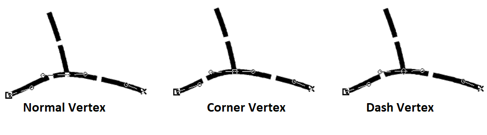
Edit a Vertex

To edit a vertex, select the Select Object and Edit Vertex editing mode. You will then be able to move, delete or change the type of vertex.
For point objects, the middle of the symbol is represented by a large square ![]() . For line and area objects, the first point of the object is represented by a large square
. For line and area objects, the first point of the object is represented by a large square ![]() , vertices by small squares
, vertices by small squares ![]() , and the last point of the object by a cross X. With Bézier curves, circle symbols
, and the last point of the object by a cross X. With Bézier curves, circle symbols ![]() are used to represent the ends of the tangents.
are used to represent the ends of the tangents.

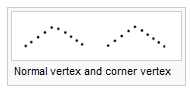
When drawing broken or dotted lines in OCAD, the dashes and spaces always have the same length. You will never get half dashes or spaces; the dashes are distributed proportionally across the entire object. However, if you add a corner vertex, the dashes before and after the vertex are calculated separately. A corner vertex is made up of two adjoining dashes; a dash point is positioned at the center of a single dash (the dash is therefore split in the middle). Corner vertices and dash points are therefore used to define the appearance of corners and intersections.
The following functions are available for editing vertices and influencing dashed lines:
 Remove Vertex: Remove a vertex from the object. Alternatively, you can press the Ctrl button and then click the vertex.
- Different point types

- Every vertex can be changed into a different kind of vertex. To do this, simply select the vertex type you want and then click the vertex object to change it.
- If a vertex of line or area objects is moved, a draft line is shown as "preview".
- Influencing dashed lines


Further information about Vertices.
Edit an Object
To edit an object, you must select the Select and Edit object mode. As soon as you have selected the object, the object frame appears with anchor points ![]() . You can now move, rotate, cut, stretch or reduce the size of the object or use the following functions:
. You can now move, rotate, cut, stretch or reduce the size of the object or use the following functions:

 Duplicate object:
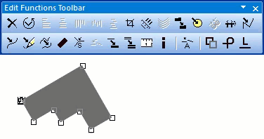

Duplicate the selected object. Alternatively, press Ctrl + C and Ctrl + V.
 Indicate direction of area pattern, point or text object:

Change the direction of the selected point or text object or the structure of the selected area object.
 Rotate Object:

Rotate the selected object around a defined rotation point.
 Move parallel:

Move the selected line object in a parallel direction or stretch or reduce the size of the selected area object.
- Move parallel with distance
- -Only for line, area and line text objects
- -Positive values move the object to the right side, negative to the left.
- -'Move': Move the selected object
- -'Duplicate': Make a copy and move the copy to the new position
 Fill or make border:

Fill in a hole in the selected area object using an area symbol or draw a border around the hole using a line symbol. Fill in the selected line object using an area symbol or combine the selected area object with an area symbol.
Holes in areas often need filling. With OCAD you can draw a border around a hole using a line symbol or fill in a hole using an area symbol.
- Select a hole by clicking it.
- Select a line or area symbol from the symbol box.
- Select Fill or make border. A border is drawn around the hole using the selected line object or it is filled in using the area object.
- After selecting a line or area object, you can combine it with another symbol. Select the object, then choose the desired line or area symbol from the symbol box and click Fill or make border. The duplicated object will be positioned above or below the selected object.
 Find selected objects:
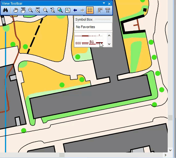

Display the selected objects in the center of the drawing window.
 Change symbol of object:
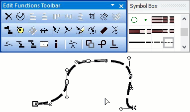

Assign a new symbol to the selected object.
 Change symbol of all objects with this symbol: Assign a new symbol to all objects with a specific symbol.
 Join: Join the ends of selected line objects that have the same symbol or the same symbol group. You can change this option in the Preferences.
- Join and merge objects
 To Curve: Change the selected freehand line into a Bézier curve. Select smooth level in toolbar.
 To Graphics: Break down the selected object into its graphical elements or display the outlines of the respective elements.
Change from drawing mode to one of the editing modes (Select and Edit object or Select Object and Edit Vertex) to edit an object. Click the Select and Edit object or Select Object and Edit Vertex button to do this. The cursor appears as either a solid or transparent arrow.
- A context menu appears when you press the right mouse button and you can change from drawing mode to editing mode and vice-versa. By deactivating the Context menu option under OCAD Preferences, GUI in the Options menu you can switch from drawing mode to editing mode, and vice-versa, by simply clicking the right mouse button.
- If an object is moved or stretched, a draft line is shown as "preview".
- Objects can be moved by clicking inside the object and moving the mouse after the object got selected. If the mouse is in a correct spot, it changeds to an cross shaped cursor
 .
.
Snapping
Tips with Keyboard and Mouse
Drawing
- Continue an existing line: Press the Shift key and click the end point of the line to be continued. This can be used instead of the
 Merge function.
 - Draw horizontal or vertical lines: Press the Alt key while drawing. The line snaps in a vertical or horizontal direction. This can be useful when drawing a border or north lines. This function is also available in the OCAD 12 CS Edition.
- Following Existing Objects: Hold the Ctrl key and click with the Left Mouse Button a point on the line to be followed. The Ctrl key can be released now. Keep the Left Mouse Button pressed and release it at the point the following shall stop. The drawing of the line can be continued now.
- Change drawing mode during drawing and editing: Press the Tab key until the desired drawing mode appears to change the drawing mode.
Editing
- Delete Vertices from line or area objects: Hold the Ctrl key and click the vertex with the Left Mouse Button. See also: Remove Vertex Tool
- Add Normal Vertices to line or area objects: Hold the Shift and the Ctrl key pressed and click the corresponding point on the line with the Left Mouse Button. See also:
 Add Normal Vertex Tool
 - Select an object under a already selected object: Hold the Alt key and click the object above the object to be selected. This function only has an effect if you are clicking near a Vertex of the object above.
- Move the selected object: Use the Arrow keys to move a selected object. For more information about selecting and moving objects visit the Select page.
- Select multiple objects: Hold the Shift key and click the objects to be selected one after another. As an alternative, drag an area with the Right Mouse Button in the
 Select and Edit Object or
  Select Object and Edit Vertex mode to select all objects which are in it. Read the Select Multiple Objects article for more information.
Cutting
- Select next object: Select a line object and choose the
 Cut function. If you press the Alt key, the cursor changes to the Select Object and Edit Vertex mode. Keep the Alt key pressed and click the next object you want to cut. Release the Alt key and continue with the cutting.
 - Insert a virtual gap: Select a line object and choose the Cut function. If you press the Ctrl key while cutting, a virtual gap is inserted. A virtual gap is graphical gap only: the line is not interrupted.
- Dashed line: Insert a gap at the cutting point: Select a dashed line object and choose the Cut function. Hold the Shift key while cutting a dashed line to insert a gap with the same length, as the other gaps in the dashed line, at the cutting point.
Back to Main Page
Previous Chapter: Import Files
Next Chapter: Select