Example Dashed Line with Dots
Jump to navigation
Jump to search
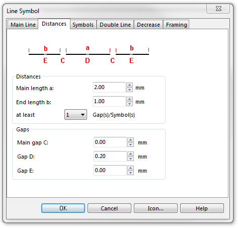
To create this line symbol, enter the following parameters to a newly created line symbol:
Main Line
- Line color: black
- Line width: 0.2 mm
Distances
- Main length a: 2.0 mm. This is the distance between the dots (from center to center).
- End length b: 1.0 mm. This must be half the length of the main dash.
- Gap D: 0.2 mm. This is the length of the gap.
Symbols
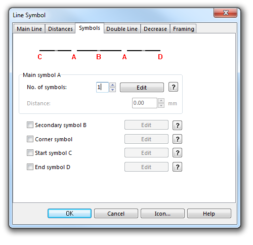
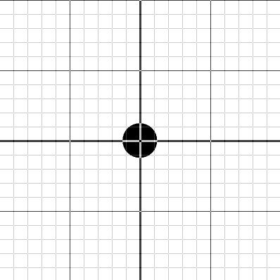
- No. of symbols: 1. Click the Edit button to open the Symbol Editor, where you can draw the dot at the coordinates 0/0.
Download link: Example_DashedLineWithDots.ocd
Back to the Create a New Line Symbol page.


