Colors
Colors 


This function has limitations in the OCAD Viewer
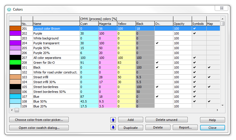
Choose this command in the Map menu to define the colors and spot colors of the map. The Colors dialog box is displayed. In this dialog all colors which you can use for the map are listed, can be edited, created or deleted.
The colors are rendered on the screen and on the printer from the bottom up. The color on the bottom is rendered first and the color on the top is rendered last. Therefore, an object A with a color, which is below the color of another object B, appears behind object B on the map.
The table contains 18 columns:
Number and Name
The first column provides you with a preview of the color defined in the corresponding row. The second and the third column are defined as follows:
- No.: In this column the color number is displayed. Each color must have a number between 0 and 32000. This number can be changed by clicking on it.
- Name: In this column a name with up to 45 characters must be given to each color. This name can be changed by clicking on it.
CMYK (process) colors
The CMYK (Cyan, Magenta, Yellow, Key (Black)) values of the color are displayed in those 4 columns. These values can be changed by clicking on it. The color preview will be updated immediately.
Overprint
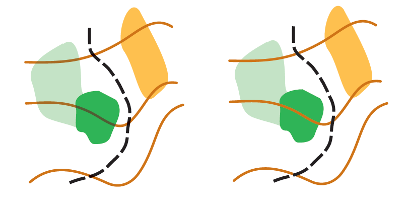
In the Ov. column you can check the Overprint option. When overprinting is chosen for a color, the CMYK separations are not omitted (i.e. the CMYK seperations are printed/rendered under the color you overprint). This makes this color appearing darker when it is printed on another color. The following example should illustrate this:
In the figure on the left side, overprinting for brown and black colors is active. In contrast, on the right side, overprinting is disabled for those colors. You can see that the brown contour lines appear darker in the green areas. Furthermore, there is a similar effect when the black path crosses the contour lines.
It is noticeable that the contour lines do not appear darker when crossing the yellow area. This is due to the fact that the brown color as well as the yellow color have a cyan value of 0. Overprinting has therefore only an effect, if the upper color has at least one CMYK value which is 0 and, at the same time, this value is greater than 0 in the lower color.
In OCAD the overprinting effect is not shown. Overprinting affects only Color AI, EPS and PDF files as well as CMYK separations. Overprinting is also supported by some PostScript printers.
![]() To show overprinting effect when printing PDF files from Adobe Acrobat Reader: Activate the Simulate overprint option in the Advanced Printer Settings .
To show overprinting effect when printing PDF files from Adobe Acrobat Reader: Activate the Simulate overprint option in the Advanced Printer Settings .
Opacity
In this column the opacity of the color in percentage can be entered by clicking the value.
An opacity value of 0 means that the color is not visible.
An opacity value from 1 to 99 means that the color is transparent with the corresponding intensity.
An opacity value of 100 means that the color is opaque.
Black with 100%, 50% and 0% opacity.
Usage
If the Symbol column is checked, the color is used in at least one symbol.
If the Map column is checked, the color is used in at least one map object, including Image and Graphic Objects.
Spot Colors
Spot colors are used if the map is printed with PMS (Pantone) colors. If the map is printed with 4 colors (CMYK), spot colors needn't be defined.
You can define a spot color value for each color. Click in the corresponding field and enter a value in percentage.
- A value of 100 means that the color appears black on the separation.
- A value of 0 means that the color appears white on the separation and erases any black color.
- An empty field means that the color has no effect on the separation.
![]() The colors are rendered on the separation from the bottom up. The lowest color in the list is drawn first and the color on top of the list is drawn last. Therefore if you put 0 in one row, only colors below this row are erased.
The colors are rendered on the separation from the bottom up. The lowest color in the list is drawn first and the color on top of the list is drawn last. Therefore if you put 0 in one row, only colors below this row are erased.
![]() Putting a 0 is especially important for streets in order to enable automatic cleaning up of crossings. The color of the street infill must be above the color of the street sidelines. And in the row of the infill there must be a 0 for the spot color of the sidelines.
Putting a 0 is especially important for streets in order to enable automatic cleaning up of crossings. The color of the street infill must be above the color of the street sidelines. And in the row of the infill there must be a 0 for the spot color of the sidelines.
To create, edit and delete spot colors choose the Define Spot Colors item in the Map menu.
Functions
- Move Up: Click the Move Up icon to move the selected color one row upwards in the color table.
- Move Down: Click the Move Down icon to move the selected color one row downwards in the color table.
- Add: Click this button to add a new color.
- Duplicate: Click this button to duplicate the selected color. The duplicated color is inserted below the selected color.
- Delete unused: Click this button to delete all colors that are neither used in any symbol nor any map object.
- Delete: Click this button to delete the selected color.
- Report: Click this button to save a report of the colors as a Word, Excel, Html or Text file. Open the report with the Open Recently Exported Documents command from the File menu.
- Choose color from Color Picker: Click this button to edit the selected color with the Color Picker.
- Open color swatch dialog: Click this button to compare the colors from the current opened OCAD file with a color swatch from a reference file.
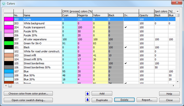
![]() If you have a map with a lot of objects, it may take some seconds until the Color dialog appears. OCAD is checking through all objects to find all colors used in the symbols and in the map. If you want OCAD to display the Colors dialog immediately, press the Shift key when choosing Colors in the Map menu. OCAD opens the dialog instantly and hides the Symbol and Map columns as well as the Delete unused button. This dialog looks as follows:
If you have a map with a lot of objects, it may take some seconds until the Color dialog appears. OCAD is checking through all objects to find all colors used in the symbols and in the map. If you want OCAD to display the Colors dialog immediately, press the Shift key when choosing Colors in the Map menu. OCAD opens the dialog instantly and hides the Symbol and Map columns as well as the Delete unused button. This dialog looks as follows:
Load Colors From 


Choose this command in the Map menu to load a color table from a different OCAD-File. The Load Colors From dialog box is displayed. Choose a map file which the color table shall be loaded from. Click the Open button to continue. Another Load Colors From dialog box appears. You have two options:
- Replace existing colors: Choose this option to overwrite the existing color table of the current map with the new one.
- Add to existing colors: Choose this option to add the new colors to the existing color table.
Click the OK button to finish.
Load Colors and Symbols From 


Choose this command in the Map menu to load a symbol set from a different OCAD-File. The Load Colors and Symbols From dialog box is displayed. Choose a map file which the symbol set shall be loaded from. Click the Open button to continue. Another Load Colors and Symbols From dialog box appears. You have two options:
- Replace existing colors and symbols: Choose this option to overwrite the existing symbol set and color table of the current map with the new ones.
- Add to existing colors and symbols: Choose this option to add the new symbols and colors to the existing ones.
You have the option to use a CRT-File to import the symbol set. In the first column of the cross reference table the symbol numbers of the current map are listed. In the second column symbol numbers of the other OCAD-File are listed, namely those numbers of symbols, which the current symbol has to be replaced with. As an example, a CRT row which is defined as 526.000 813.001, means that the symbols of all objects with the symbol number 526.000 will get the symbol of the other OCAD-File with the number 813.001.
Visit the Cross Reference Table page to get detailed information about using CRT-Files. Click the Load button to load a CRT-File.
Click the OK button to finish.
![]() The error message "Cannot import symbol" appears if OCAD was not able to load a symbol. The Load Colors and Symbols From process is aborted.
The error message "Cannot import symbol" appears if OCAD was not able to load a symbol. The Load Colors and Symbols From process is aborted.
Previous Chapter: Create a New Map
Next Chapter: Create a New Symbol
Back to Main Page
To the Map page.


