Migration von unstrukturierten DTP-Karten
Anpassung von unstrukturierten Desktop-Publishing-Karten in ein GIS
Viele Karten werden mit einer Desktop-Publishing (DTP) Software, wie Macromedia Freehand, Adobe Illustrator oder CorelDraw erstellt. Der Vorteil dieser Softwareprogramme ist, dass diese eine grosse Auswahl an Zeichnungs- und Bearbeitungswerkzeugen aufweisen, sie eine flexible Ebenenstruktur für Karte und Kartenlayout besitzen und dass sie im Vergleich zu GIS (Geographic Information System) billiger sind. DTP-Karten sind jedoch limitiert, um auf dem neuesten Stand der Technik der digitalen Kartografie zu bleiben. Die grössten Nachteile sind:
- Verzerrung: DTP-Karten sind meistens auf Grund von falsch platzierten Kacheln oder der Vektorisierung von kaum angepassten Hintergrundkarten komplett oder teilweise verzerrt. DTP-Programme haben keine Werkzeuge, um die Verzerrung mit Hilfe eines Koordinatenbezugsystems oder Referenzpunkten aufzuheben.
- Keine Georeferenzierung: DTP-Softwares besitzen kein eigenes Koordinatenbezugssystem, um georeferenzierte Kartendaten auszutauschen. Dies schränkt die Nutzung von georeferenzierten Daten (z.B. Geodatenserver, Geo-Portale und OpenStreetMap-Daten) ein, was heutzutage eine wichtige Funktion ist, entweder um die Karte aufzuwerten, sie für die Navigation zu verwenden oder für GPS-Lokalisierungen.
- Unstrukturierter Kartenaufbau: Die flexible Ebenenstruktur und Symboldefinitionen führen zu einem schlechten Aufbau. Einzelne Kartenobjekte können einfach von der Ebene an einen anderen Ort verschoben werden, um eine bessere grafische Erscheinung zu erzielen (z.B. Brücken und Tunnel). Ausserdem werden Punktobjekte als Flächenobjekte dargestellt. Das Resultat ist, dass solche Karten viele überflüssige Daten aufweisen, die einerseits mühsam zu verwalten sind und andernseits nicht richtig in ein GIS passen.
- Keine spezifischen kartographischen Zeichnungs- und Bearbeitungswerkzeuge: DTP-Softwares besitzen keine eigenen spezifischen kartographischen Zeichnungs- und Bearbeitungswerkzeuge, wie Linienverfolgung, automatisches Blockout von Strassenkreuzungen oder Beeinflussung von gestrichelten Linien, um die effiziente Kartenproduktion zu unterstützen.
- Keine Datenbankverbindungen: DTP-Softwares besitzen keine eigenen Datenbankverbindungen, um zusätzliche Informationen von Kartenobjekten, wie Datum der Aufnahme, Herausgeber oder letzte Bearbeitung, zu speichern.
Viele Kartenveröffentlicher produzierten am Anfang der Zeit der digitalen Kartografie tausende von DTP-Karten. Heute fürchten sie, dass sie in eine Sackgasse geraten können, denn DTP-Softwares haben klare Nachteile und werden nicht mehr unterstützt.
Aus diesem Grund entwickelte OCAD AG in Zusammenarbeit mit Huber Kartografie, München DE einen Arbeitsablauf in der OCAD-Software, um Daten von DTP-Karten durch eine Anpassung in die Kartografie-Software oder sogar in ein GIS zu erhalten: Zu erst muss die DTP-Karte als PDF-Datei importiert werden. Danach wird die Verzerrung aufgehoben und die Karte wird georeferenziert. Im nächsten Schritt werden die importierten Ebenen in Symbole eines Symbolsatzes der Kartografiesoftware umgewandelt. Diese Umwandlung hat das Resultat, dass überflüssige Daten entfernt werden. Punktobjekte, welche immer noch als Flächenobjekte abgebildet werden, müssen in einzelne Punktobjekte umgewandelt werden. Alle Kartenobjekte können nun mit einer Datenbank verbunden werden. Mit diesem Arbeitsablauf wird die DTP-Karte so strukturiert, dass sie in eine GIS-Umgebung passt oder mit weiteren Geodaten verbessert und mit spezifischen kartografischen Zeichnungs- und Bearbeitungswerkzeugen in der Software angepasst werden kann. Dieser Arbeitsablauf wurden von Huber Kartografie erfolgreich implementiert.
Ganzer Text (in Englisch): http://www.ocad.com/public/2011-02-11_longTxt_icc2011_migrationDTPmaps_intoGIS.pdf
OCAD-Datei öffnen
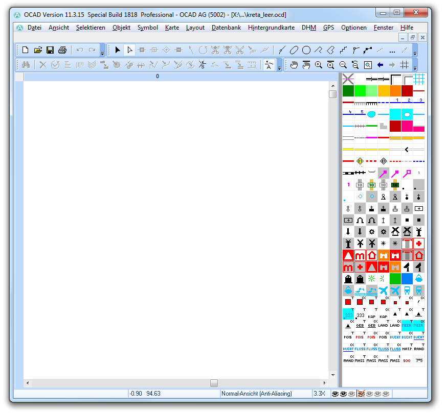
Öffnen Sie die Datei kreta_leer.ocd. Die Datei befindet sich im Verzeichnis kreta_ocad.
Kartenmassstab bestimmen
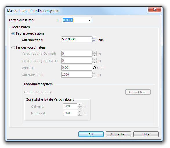
Setzen Sie den Kartenmassstab auf 1:100000 (Karte -> Massstab und Koordinatensystem).
-> OK
Symbolsatz definieren
In der OCAD-Datei wurde bereits ein Symbolsatz definiert. In dieser Anleitung wird die Definition des Punktsymbols Interessanter Ort beschrieben.
Eingescannte legende als Hintergrundkarte öffnen
Öffnen Sie die TIFF-Datei Legende_kreta.tif aus dem Verzeichnis lrete_backgroundmaps als Hintergrundkarte (Hintergrundkarte -> Öffnen).
Neues Symbol erstellen
Symbol -> Neu
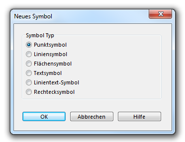
Wählen Sie im Dialog Neues Symbol die Option Punktsymbol:
-> OK
Geben Sie Symbolnummer und -beschreibung ein. Klicken Sie auf Bearbeiten:
Der Symboleditor erscheint.
Ansicht -> Ganze Karte zeigen und Bildschirm-Gitter anzeigen
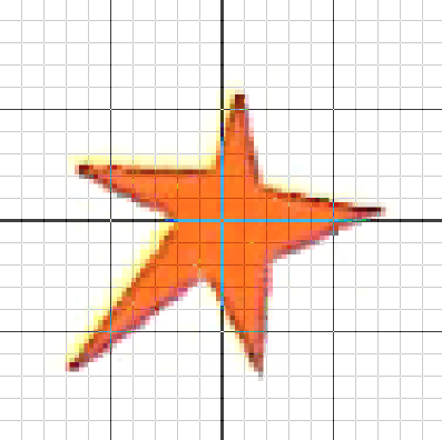
Im nächsten Schritt muss das Legendensymbol im Ursprung der Koordinaten des Symboleditors platziert werden (roter Pfeil in Abbildung):
Hintergrundkarte -> Abstimmen (Shortcut F9):
- Mausklick auf das Symbol Sehenswürdigkeit in der Hintergrundkarte.
- Mausklick auf den Mittelpunkt der Koordinaten des Editors.
- Drücken Sie Enter, um den Vorgang ausuzuführen.
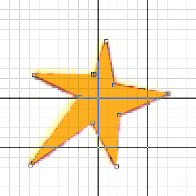
Selektieren Sie die Geometrie Fläche und die Farbe 0: Pikto Orange im Symbol-Editor:
Zeichnen Sie danach das Symbol mit dem Geraden-Modus nach.
-> Schliessen Sie den Symboleditor.
Die Dialogbox Punktsymbol wird wieder angezeigt.
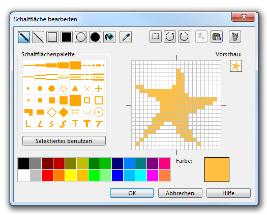
-> Schaltfläche
Erstellen Sie ein Symbol-Icon:
-> OK
Die Dialogbox Punktsymbol wird wieder angezeigt.
-> OK
Entfernen Sie die Hintergrundkarte (Hintergrundkarte -> Verwalten):
-> Entfernen und Dialog Schliessen.
OCAD Lernvideos:
DTP-Karte als PDF importieren
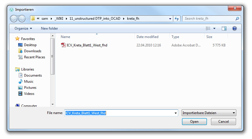
Import PDF file ICV_crete_Mapsheet1_West_fhd.pdf from the directory crete_fh (File -> Import).
-> Open
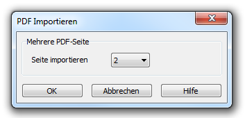
The import side which should be imported must be specified, because it is multi-page PDF.
-> OK
The import map is displayed. However the map is not georeferenced.
Georeferenzierte Hintergrundkarte öffnen
Open the georeferenced TIFF file crete_osm_import_100000.tif from the directory crete_osm as background map (Backgroundmap -> Open).
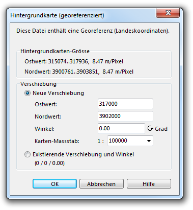
Because it is a georeferenced background map, a dialog box appears with the question if the new shift (horizontally and vertically according to the Easting and Northing) shall be used as the card center.
-> Ok
The Crete map the the georeferenced background map are shown. But the Crete map is still not correctly georeferenced.
The interactive georeferencing from the Crete map success in the next section.
Georeferenzierung und Rubbersheeting
Change the View into Draft Mode (View -> Draft Mode).
In the toolbar, a bar appears with two controllers. With the upper controller (M=Map) can adjust the transparency of the map and with the lower controller (B=Background Map) can adjust the transparency of the background map.
Grobe Abstimmung mit Affintransformation
In a first step, the imported map was fitted coarse with an affine transformation in the georeferenced background map (Map -> Transform -> Affine).
- Mouse click into the map.
- Mouse click on the appropriate point on the background map.
- Execute transformation with enter key.
![]() At the affine transformation the maximum of 12 reference points can be defined, by repeating step 1 and 2 until the transformation is triggered by the enter button.
At the affine transformation the maximum of 12 reference points can be defined, by repeating step 1 and 2 until the transformation is triggered by the enter button.
Feinabstimmung mit Rubbersheeting
In the second step the map fitted as exactly as possible with rubbersheeting transformation on the georeferenced background map (Map -> Transform -> Rubbersheeting)
OCAD learning videos:
First the rubbersheeting perimeter must be determined (Define -> Draw rubbersheeting perimeter on map)
Perimeter is displayed as a blue frame in the drawing area:
When a perimeter is defined, rubbersheeting points can be added interactively or from loaded from a file.
Add rubbersheeting points interactive:
- Mouse click into the map.
- Mouse click on the appropriate point on the background map.
Rubbersheeting points are shown with a red and green crosshair and a blue connection line. In the transformation, the objects moved from the red to the green dot.
Depending on the needs the points can be deactivated, removed or saved. The deactivation is done by mouse click on the first column in the table. Unused points are shown gray in the drawing area.
Execute the transformation by clicking the Transform button.
If the result is satisfactory, the dialogue can be closed.
Otherwise there are the following possibilities:
- Undo the transformation an optimize rubbersheeting points (add, deactivate, delete)
- Use the result as a starting point for further transformation with new points.
PDF-Bildobjekte in OCAD-Objekte transformieren
Automatische Konvertierung
With the function Convert Imported Layers to Symbols (Map -> Convert Imported Layers to Symbols) icons can be automatically converted due to their affiliation with the appropriate symbol into OCAD objects with the appropriate symbol.
In the dialog box Convert Imported Layers to Symbols the translation table crete.crt from the crete_crt directory needs to be loaded.
-> Execute
Manuelle Konvertierung
In the automatic conversion wrong symbols assigned from objects lying on wrong layers. In the example below, the Greek name of the attraction Tilissos is falsely attributed to the layer with the black instead of red font.
Select object:
Select correct symbol from symbol box:
Click Change Symbol in stadard toolbar to assign the object to the right symbol
Flächensymbole in OCAD-Punktsymboleumwandeln und redundante Objekte löschen
In DTP programms point objects are often defined as an area object. Thus make a situation worse by the map tracking. Therefore, these objects should be converted into point objects. These have only coordinates and can be easily deleted or moved at a tracking.
In the automatic conversion these objects have been transformed as a workaround in area objects (for example 1601.1 chapel area). In the symbol set they are defined as single point and area symbols. First select all objects with the area symbol 1601.1 chapel area (Symbolbox -> symbol 1601.1 chapel area -> context menu -> Select Objects by Symbol).
Then the conversion occur in a point object(Map -> Convert Area or Line Objects to Point Objects), while the symbol 1601.1 chapel area have been selected.
-> Execute
![]() In case of imported signatures, consisting of multiple surfaces, before the conversion the surplus areas have to be removed, so that the equivalent to only one object is created to the appropriate place.
In case of imported signatures, consisting of multiple surfaces, before the conversion the surplus areas have to be removed, so that the equivalent to only one object is created to the appropriate place.
This process is explained using the example of the windmill. The imported windmill signatures are part of five faces: one tower and four rotor blades:
Befor converting into a point object the four rotor blades of all windmills have to be selected and deleted
Select the symbol 1702.1 windmill area in sybmol box.
Choose the function Select Object by Property (Map -> Select Objects by Property).
Settings: Select: Object with a selected symbol Condition: Number of vertices = 4
-> Select and Close dialog box
The rotor blades of all windmills were selected.
Delete selected objects with Delete button.
The ramaining area objects can now be transformed into point objects as described in the first part of the chapter.
Redundante Objekte löschen
There are redundant objects in the immported map. So, for example, streets consist of two or more geometrically identical lines. In OCAD these complex lines can be mapped with a line object. Thus the redundant objects be unnecessary and can be deleted.
First select all objects (Symbol box -> Symbol 1.0 Skelett -> context menu -> Select Objects by Symbol).
Delete selected objects with delete button or .
Datenbank anhängen
In OCAD 10 Proffesional is it possible to connect the map or its objects to a database. A new database must be define (Database -> Manage Database Connections)
-> New
Give the connection a name and select the option Use existing datasource
-> OK
Select a database file.
-> Browse
Open the file crete.cls from the directory crete_db.
Select the table wamu§ and the field ID as a key field.
Select all water mills (Symboleditor -> context menu -> Select Objcts by Symobls:
Create database connection für select water mills (Database -> Create and Update Records).
Dataset: Water mills
-> OK
Search the water-mill due to the key field (Find -> enter Key)
->OK
Edit the corresponding database entries in the database box:
GIS exportieren ( SHP oder DXF)
The Map or parts thereof can be exported as shape file or DXF and reused in geographical information system or CAD programs.
File -> Export -> Shape -> Point objects -> Objects in dataset: Water mills
-> OK
Save file as crete_wamu.shp
Für Google Earth exportieren (KMZ Google Earth Raster)
The map or parts thereof can also be exported as a KMZ file and reused in Google Earth or GPS device. For this export a coordinate system must be absolutely defined.
Map -> Set Scale and Coordinate System -> Choose -> Coordinate system: UTM -> Zone: Zone 35 North
File -> Export -> KMZ Google Earth (Raster)
Make export settings and choose map sector:
-> OK
Save export file as crete.kmz:
-> Save
Anhang
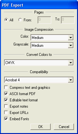
Settings of the PDF export from Freehand, for the best import into OCAD:
