Ein neues Punktsymbol erstellen: Unterschied zwischen den Versionen
FBO (Diskussion | Beiträge) Keine Bearbeitungszusammenfassung |
FBO (Diskussion | Beiträge) Keine Bearbeitungszusammenfassung |
||
| Zeile 2: | Zeile 2: | ||
[[File:Pro40px.PNG|This function is available in OCAD 11 Professional.|link=https://www.ocad.com/en/products/ocad-for-cartography]][[File:Std40px.PNG|This function is available in OCAD 11 Orienteering Standard.|link=https://www.ocad.com/en/products/ocad-for-orienteering]][[File:Sta40px.PNG|This function is available in OCAD 11 Starter.|link=https://www.ocad.com/en/products/ocad-for-orienteering]][[File:CS40px.PNG|This function is available in OCAD 11 Course Setting.|link=https://www.ocad.com/en/products/ocad-for-orienteering]] | [[File:Pro40px.PNG|This function is available in OCAD 11 Professional.|link=https://www.ocad.com/en/products/ocad-for-cartography]][[File:Std40px.PNG|This function is available in OCAD 11 Orienteering Standard.|link=https://www.ocad.com/en/products/ocad-for-orienteering]][[File:Sta40px.PNG|This function is available in OCAD 11 Starter.|link=https://www.ocad.com/en/products/ocad-for-orienteering]][[File:CS40px.PNG|This function is available in OCAD 11 Course Setting.|link=https://www.ocad.com/en/products/ocad-for-orienteering]] | ||
Select the '''New''' command in the '''Symbol''' menu. Choose the '''Point symbol''' option in the '''New Symbol''' dialog box to create a new point symbol | Select the '''New''' command in the '''[[Symbol]]''' menu. Choose the '''Point symbol''' option in the '''New Symbol''' dialog box to create a new point symbol. | ||
[[File:NewSymbol.JPG]] | [[File:NewSymbol.JPG]] | ||
The '''Point Symbol''' dialog appears. | |||
===Point Symbol Dialog=== | ===Point Symbol Dialog=== | ||
[[File:NewPoint.JPG|Create a New Point]] | [[File:NewPoint.JPG|Create a New Point]] | ||
Version vom 24. August 2012, 10:36 Uhr
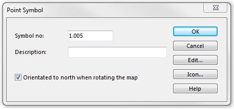
Select the New command in the Symbol menu. Choose the Point symbol option in the New Symbol dialog box to create a new point symbol.
The Point Symbol dialog appears.
Point Symbol Dialog

Enter a number between 0.001 and 999999.999 in the Symbol number field.
Enter a description of the new symbol in the Symbol description field.
Check the Orientated to north when rotating the map option if you want that the symbol always stays orientated to north when you use the Rotate function.
Click the Edit button to edit the object. The Symbol Editor appears.
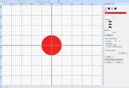
Symbol Editor
The main window changes to the symbol editor...
- ... when you create or edit a point symbol.
- ... when you create or edit a symbol for a structured line.
- ... when you create or edit a symbol for a structured area.
When you change to the symbol editor, the magnification changes to 32x and the coordinate (0,0) is in the center of the screen. A number of menu functions are disabled when working in the symbol editor. However, you can open and adjust a Background Map if you have a scanned image of the desired symbol.
On the right side of the drawing area the Symbol Editor menu is displayed. In the Symbol element style part of this menu you can make drawing adjustments of symbol elements.
Type
You can choose between four symbol element types: ![]() Line,
Line, ![]() Area,
Area, ![]() Circle or
Circle or ![]() Dot (Filled Circles)..
Dot (Filled Circles)..
Color
Choose a color from the Color dropdown menu. These colors are the same colors as in the Colors dialog of the Map menu and have to be defined before opening the Symbol Editor. Learn more about defining and editing colors on the Colors page. If you draw a structure for an area and this area has a background color, you must choose a color which is above the background color in the color table. Otherwise the element will be covered by it.
Line width
If you have chosen a Line or a Circle as a symbol element type, enter a line width in mm in this field. Note that the Line width is set to zero by default and with a Line width of zero the drawn symbol element is invisible!
Line style
If you have chosen a Line as a symbol element type, you can choose here how the corners and line ends of the line symbol element shall appear.
Diameter
If you have chosen a Circle or a Dot as a symbol element type, enter here the diameter the symbol element is meant to have. For circles, this diameter includes the line width of the circle line.
When you made all those adjustments you can start drawing the symbol element. You can draw any number of elements for one symbol. The number of vertices of all elements is limited by 32768.
Line: A line symbol element can be drawn with the regular drawing modes (curve, ellipse, circle etc.).
Area: An area symbol element can be drawn with the regular drawing modes (curve, ellipse, circle etc.) as well.
Circle: A circle symbol element have to be placed like a point object where the placement point is the middle of the circle.
Dot: A dot symbol element have to be placed like a point object where the placement point is the middle of the filled circle.
The center of the drawing area (0mm/0mm) is equal to the center of the point object.
You can change the drawn symbol elements by selecting them and making adjustments in the Symbol Editor menu. Click the Change button at the bottom of the Symbol element style field to apply all changes to the symbol elements. It is also possible to add or remove vertices (Vertices) or use nearly all editing functions (Edit Object).
In the Scale selected symbol element part of the Symbol Editor menu you can scale the selected symbol element(s):
Scale factor: Enter a scale factor in percentage.
Scale center: Use either the center of the symbol (center of the drawing area (0/0)) or the center of the symbol element (x/y) as a scale center.
Scale line width: Check this option to extend or reduce also the line width.
Click the Scale up/down button to scale the selected symbol element(s).
Select a symbol element and click the Center selected symbol element button to move it to the center of the drawing area (equals center of the symbol).
Click the Make screenshot for symbol icon button to make a screenshot and use it as symbol icon.
Drawing symbols for structured lines
When drawing symbols for a line, imagine that the line goes from left to right on the x-axis. If you want a tag to point to the right side of the line, draw it downwards from the origin (0, 0); if it should point to the left side, draw it upwards.
Drawing symbols for structured areas
If the area symbol has a background color, this background color is also shown. Note that the background color must be below the color of any elements in the color table, otherwise these elements are covered by the background color.
When you draw an element, it is also shown in gray in the neighboring fields to get a better impression of the structure.
Click the Close button when you are finished with drawing the symbol. The Point Symbol dialog box appears again. Click the Icon button to edit the icon manually in the Icon Editor. Click the OK button to save all changes and quit the dialog. The new symbol appears in the symbol box.

