Ein neues Linientextsymbol erstellen: Unterschied zwischen den Versionen
FBO (Diskussion | Beiträge) (Created page with "File:Space.PNGThis function is available in OCAD 11 Professional.|link=https://www.ocad.com/en/products/ocad-for-cartography[[File:Std40px.PNG|This fu...") |
FBO (Diskussion | Beiträge) Keine Bearbeitungszusammenfassung |
||
| Zeile 1: | Zeile 1: | ||
[[File:Pro40px.PNG|This function is available in OCAD 11 Professional.|link=https://www.ocad.com/en/products/ocad-for-cartography]][[File:Std40px.PNG|This function is available in OCAD 11 Orienteering Standard.|link=https://www.ocad.com/en/products/ocad-for-orienteering]][[File:Sta40px.PNG|This function is available in OCAD 11 Starter.|link=https://www.ocad.com/en/products/ocad-for-orienteering]][[File:CS40px.PNG|This function is available in OCAD 11 Course Setting.|link=https://www.ocad.com/en/products/ocad-for-orienteering]] | |||
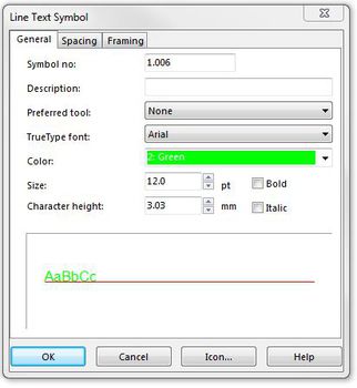
[[File:LineTextSymbol.JPG|miniatur|350x350px|right|new line text symbol]] | [[File:LineTextSymbol.JPG|miniatur|350x350px|right|new line text symbol]] | ||
Version vom 12. September 2012, 10:37 Uhr
You can create line text symbols with OCAD. The following options are available:
- General: Used to define the font color, type and size.
- Spacing: Used to define the letters, word spacing and text positioning.
- Framing: Used to define the framing
- Select New in the Symbol menu.
- Select the symbol type Line Text Symbol. The Line Text Symbol dialog box appears.
- Enter a number between 0.001 and 999999.999 in the Symbol number field and a symbol description in the Description field.
- Click Edit. The symbol editor appears.
- If required, configure the options 'general', 'spacing' and 'framing' for the text line symbol.
- Once you have defined the line text symbol, select Icon in the dialog window. The Edit Icon dialog window appears.
- Draw the icon in the 22 x 22 pixel matrix field using the various drawing tools.
- When you are finished, click OK twice. The new symbol appears in the symbol field.
General
- Preferred tool: Choose here a drawing mode. Each time the symbol is selected, the drawing mode changes to this drawing mode. Choose None to switch off this feature.
- TrueType Font: Choose a font for the text symbol. All TrueType fonts installed in Windows are listed. You cannot use raster fonts or Adobe Type Manager fonts.
- Color: Choose the color for the text.
- Size: Choose the size in points for the text. Alternatively, you can enter the character height in millimeters in the box Character height.
- Character height: Enter here the height of the character 'B' in millimeters. Alternatively you can enter the size of the font in points in the box Size.
- Bold: Check this box for bold text.
- Italic: Check this box for italic text.
![]() The error message: "Font not found" appears if a font is chosen that is not installed on the PC. The font needs to be installed on the PC or another font must be chosen. Otherwise the font Arial is used.
The error message: "Font not found" appears if a font is chosen that is not installed on the PC. The font needs to be installed on the PC or another font must be chosen. Otherwise the font Arial is used.
Line text symbols are used for text along curved lines.
Line text can be written along any line, including curved lines. To draw a line text object you must define a line text symbol and then:
- Select the line text symbol
- Draw a line in any drawing mode (curve, ellipse, circle etc.)
- After terminating the line, an insertion line appears and you can directly type the text on the keyboard.
- If the text goes in the wrong direction, click the Reverse line button.
Spacing
Choose this page to define spacing and alignment for a line text symbol.
- Character spacing: Enter here a distance to be inserted between characters. If you enter 100% a space character is inserted between characters.
- Word spacing: Enter here the distance between words. 100% means that a normal space character is used between words.
- Alignment: Choose here how the text is aligned along the line. All line means that the text is distributed along the entire line. With this option the letter-spacing will be adapted to the length of the line text object.
Create a New Rectangle Symbol 


You can create rectangle symbols with OCAD.
- Select New in the Symbol menu.
- Select the symbol type Rectangle Symbol. The Rectangle symbol dialog box appears.
- Enter a number between 0.001 and 999999.999 in the Symbol no. field and a symbol description in the Description field.
- Choose a Line color and Line width, a Drawing mode and set the Grid and Numbering options.
- Once you have defined the rectangle symbol, click Icon to open the Edit Icon dialog box.
- Draw the icon in the 22 x 22 pixel matrix field using the various drawing tools.
- When you are finished, click OK twice. The new symbol appears in the symbol box.
Rectangle symbols
Rectangle symbols are used to draw rectangular frames (around the entire map or around parts of the map). A special use for Rectangle symbols is punch boxes for orienteering maps.
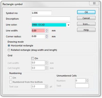
- Symbol no.: Enter here a number between 0.001 and 999'999.999 for the symbol. Each symbol requires a unique number.
- Description: Enter here a description for the symbol. The description is displayed when selecting the symbol or when selecting an object with that symbol.
- Line Color: Choose a color for the frame.
- Line width: Enter a line width for the frame.
- Corner radius: If you want the frame to have round corners, enter the corner radius here (measured to the center of the line), otherwise enter 0 here.
Drawing mode
- Horizontal rectangle: Activate this option if you want to draw only horizontal rectangles.
- Rotated rectangle: Activate this option if you want to draw rotate rectangles.
Grid
- On: Activate this field if you want to draw punch boxes for orienteering maps.
- Cell width / Cell height: Enter the desired width and height for the cells.
Numbering
- On: Activate this field if you want numbers for the grid.
- Numbered from the bottom: Normally the cells are numbered starting from the top row. Check this box to start numbering from the bottom row.
- Text size: Choose the size in points for the text.
- Unnumbered Cells
- Number: Enter here the number of cells used as reserved fields.
- Text: Enter here up to 3 characters which appear instead of the number in the reserved fields. If you want all cells numbered enter here 0.

