Ein neues Liniensymbol erstellen: Unterschied zwischen den Versionen
FBO (Diskussion | Beiträge) Keine Bearbeitungszusammenfassung |
FBO (Diskussion | Beiträge) Keine Bearbeitungszusammenfassung |
||
| Zeile 1: | Zeile 1: | ||
[[Category:Ein neues Symbol erstellen]][[Category:Symbol]] | [[Category:Ein neues Symbol erstellen]][[Category:Symbol]][[File:TwoDashed.PNG|750px]]<br> | ||
[[File:StoneEmbankmentTopEdge.PNG|750px]] | |||
[[File:Pro40px.PNG|Diese Funktion ist verfügbar in OCAD 11 Professional.|link=https://www.ocad.com/de/produkte/ocad-fuer-kartografie]][[File:Std40px.PNG|Diese Funktion ist verfügbar in OCAD 11 Orienteering Standard.|link=https://www.ocad.com/de/produkte/ocad-fuer-orientierungslauf]][[File:Sta40px.PNG|Diese Funktion ist verfügbar in OCAD 11 Starter.|link=https://www.ocad.com/de/produkte/ocad-fuer-orientierungslauf]][[File:CS40px.PNG|Diese Funktion ist verfügbar in OCAD 11 Course Setting.|link=https://www.ocad.com/de/produkte/ocad-fuer-orientierungslauf]] | [[File:Pro40px.PNG|Diese Funktion ist verfügbar in OCAD 11 Professional.|link=https://www.ocad.com/de/produkte/ocad-fuer-kartografie]][[File:Std40px.PNG|Diese Funktion ist verfügbar in OCAD 11 Orienteering Standard.|link=https://www.ocad.com/de/produkte/ocad-fuer-orientierungslauf]][[File:Sta40px.PNG|Diese Funktion ist verfügbar in OCAD 11 Starter.|link=https://www.ocad.com/de/produkte/ocad-fuer-orientierungslauf]][[File:CS40px.PNG|Diese Funktion ist verfügbar in OCAD 11 Course Setting.|link=https://www.ocad.com/de/produkte/ocad-fuer-orientierungslauf]] | ||
Mit OCAD können Sie sehr komplexe Liniensymbole erstellen. Ausserdem kann uns der Symboleditor fast alle Zeichnungs- und Bearbeitungswerkzeuge zur Verfügung stellen, um Liniensymbole noch einfacher zu gestalten. | Mit OCAD können Sie sehr komplexe Liniensymbole erstellen. Ausserdem kann uns der Symboleditor fast alle Zeichnungs- und Bearbeitungswerkzeuge zur Verfügung stellen, um Liniensymbole noch einfacher zu gestalten. | ||
| Zeile 10: | Zeile 10: | ||
[[File:NewLineSymbolDialog.PNG]] | [[File:NewLineSymbolDialog.PNG]] | ||
Der '''Liniensymbol'''-Dialog erscheint. Dieser besteht aus sechs Registerkarten: | Der '''Liniensymbol'''-Dialog erscheint. Dieser besteht aus sechs Registerkarten: | ||
| Zeile 20: | Zeile 19: | ||
*'''Freistellung:''' Hier können Sie Linien freistellen, sodass z.B. komplexe Linien andere Objekte trotzdem überdecken. | *'''Freistellung:''' Hier können Sie Linien freistellen, sodass z.B. komplexe Linien andere Objekte trotzdem überdecken. | ||
==Hauptlinie== | |||
[[File:MainLineDialog.PNG]] | [[File:MainLineDialog.PNG]] | ||
In der '''Hauptlinie'''-Registerkarte können Sie folgende Anpassungen vornehmen: | In der '''Hauptlinie'''-Registerkarte können Sie folgende Anpassungen vornehmen: | ||
===Symbolnummer=== | |||
Geben Sie in diesem Feld eine Symbolnummer zwischen 0.001 und 999999.999 ein. | Geben Sie in diesem Feld eine Symbolnummer zwischen 0.001 und 999999.999 ein. | ||
===Symbolbeschreibung=== | |||
Geben Sie dem Symbol eine Beschreibung (z.B. Eisenbahnlinie). | Geben Sie dem Symbol eine Beschreibung (z.B. Eisenbahnlinie). | ||
===Vorzugszeichenwerkzeug=== | |||
Sie können hier ein '''Vorzugszeichenwerkzeug''' wählen. Wenn das Symbol in der '''[[Symbolbox]]''' angewählt wird, wechselt OCAD automatisch in den entsprechenden Zeichnungsmodus. Wenn in der Dropdown-Liste '''Aus''' ausgewählt ist, bleibt OCAD beim Anwählen des Symbols im letzt aktiven Zeichnungsmodus. | Sie können hier ein '''Vorzugszeichenwerkzeug''' wählen. Wenn das Symbol in der '''[[Symbolbox]]''' angewählt wird, wechselt OCAD automatisch in den entsprechenden Zeichnungsmodus. Wenn in der Dropdown-Liste '''Aus''' ausgewählt ist, bleibt OCAD beim Anwählen des Symbols im letzt aktiven Zeichnungsmodus. | ||
===Linienfarbe=== | |||
Wählen Sie hier eine Linienfarbe der Hauptlinie. Die Dropdown-Liste enthält alle Farben, welche in der '''[[Farben|Farbtabelle]]''' definiert sind. Wenn keine Hauptlinie verwendet wird, ist es nicht nötig eine Linienfarbe zu definieren. | Wählen Sie hier eine Linienfarbe der Hauptlinie. Die Dropdown-Liste enthält alle Farben, welche in der '''[[Farben|Farbtabelle]]''' definiert sind. Wenn keine Hauptlinie verwendet wird, ist es nicht nötig eine Linienfarbe zu definieren. | ||
===Strichdicke=== | |||
Geben Sie in diesem Feld eine Strichdicke ein. Wenn Sie keine Hauptlinie anzeigen möchten, wählen Sie 0.00mm. | Geben Sie in diesem Feld eine Strichdicke ein. Wenn Sie keine Hauptlinie anzeigen möchten, wählen Sie 0.00mm. | ||
===Linienart=== | |||
Wählen Sie zwischen drei Linienarten aus. Die Linienenden und -ecken erscheinen jeweils in anderer Form. | Wählen Sie zwischen drei Linienarten aus. Die Linienenden und -ecken erscheinen jeweils in anderer Form. | ||
| Zeile 46: | Zeile 45: | ||
''Diese Abbildung ist leider nur in Englisch verfügbar.'' | ''Diese Abbildung ist leider nur in Englisch verfügbar.'' | ||
===Länge=== | |||
Geben Sie hier zwei Abstände ein: | Geben Sie hier zwei Abstände ein: | ||
* '''Abstand vom Start:''' Dieser Wert beschreibt den Abstand vom Linienanfang bis zum Hauptlinienanfang (dann wenn die Linie sichtbar wird). | * '''Abstand vom Start:''' Dieser Wert beschreibt den Abstand vom Linienanfang bis zum Hauptlinienanfang (dann wenn die Linie sichtbar wird). | ||
| Zeile 59: | Zeile 58: | ||
''Diese Abbildung ist leider nur in Englisch verfügbar.'' | ''Diese Abbildung ist leider nur in Englisch verfügbar.'' | ||
====Beispiele==== | ===Bahnlegung für den Orientierungslauf-Optionen=== | ||
[[File:Example.jpg]] '''[[Beispiel: | In Bahnlegungsprojekten steht Ihnen eine zusätzliche Option zur Verfügung, nämlich das Verwenden des Symbols als Pflichtstrecke. Besuchen Sie die '''[[Bahnlegungsobjekte hinzufügen#Pflichtstrecke hinzufügen|Bahnlegungsobjekte hinzufügen]]'''-Seite für weitere Informationen. | ||
[[File: | |||
===Beispiele=== | |||
[[File:Example.jpg]] '''[[Beispiel Durchgehende Linie]]''' | |||
: Dies ist ein Beispiel für eine einfache, durchgehende Linie.<br> | |||
[[File:FullLine.PNG|750px]] | |||
[[File:Example.jpg]] '''[[Beispiel Gestrichelte Linie mit Hintergrund]]''' | |||
: Dies ist ein Beispiel, welches die Funktionen '''Abstand vom Start''' und '''Abstand zum Ende''' verdeutlichen.<br> | |||
[[File:DashedLineWithBackground.PNG|750px]] | |||
[[File:Example.jpg]] '''[[Beispiel Autobahn]]''' | |||
: Dies ist ein Beispiel, welches die Funktionen '''Abstand vom Start''' und '''Abstand zum Ende''' verdeutlichen.<br> | |||
[[File:Motorway.PNG|750px]] | |||
[[File:Example.jpg]] '''[[Beispiel Spitze Linie]]''' | |||
: Dies ist ein Beispiel für '''Spitze Enden'''.<br> | |||
[[File:PointedLine.PNG|750px]] | |||
==Abstände== | |||
[[File:LineSymbolDistances.PNG]] | |||
In dieser Registerkarte können Sie alle Parameter für gestrichelte Linien einstellen. | |||
===Abstände=== | |||
'''Hauptlänge a'''<br> | |||
Diese Länge definiert die Länge des Hauptstriches (siehe Abbildung im oberen Teil des Dialogs, der Hauptstrich ist mit dem Buchstaben '''a''' markiert). Für gepunktete Linien geben Sie hier die Distanz zwischen den Punkten ein. | |||
'''Endlänge b'''<br> | |||
Diese Länge definiert die Länge der Start- und Endstriche (siehe Abbildung im oberen Teil des Dialogs, die Endstriche sind mit dem Buchstaben '''b''' markiert). Für gepunktete Linien sollten Sie hier 0 eingeben, um sicherzustellen, dass die Linie mit einem Punkt und nicht einer Lücke beginnt. Für Linien mit Punkten drauf geben Sie hier die Distanz vom Linienanfang bis zum ersten Punkt auf der Linie ein. | |||
[[File:Hint.jpg]] Die Endlänge wird auch vor und nach einer Ecke der Linie benutzt. | |||
'''mindestens X Unterbrüche/Symbole'''<br> | |||
Sie können hier eine minimale Anzahl (maximal 2) Lücken oder Symbole (wenn ein Hauptsymbol definiert ist) angeben, welche eine Linie beinhalten muss. Wenn Sie wollen, dass eine gestrichelte Linie immer eine Lücke hat (egal wie kurz sie ist), wählen Sie hier '''1'''. | |||
===Unterbrüche=== | |||
'''Unterbruch C'''<br> | |||
Dies ist der Hauptunterbruch und der Wert in diesem Feld definiert dessen Länge (siehe Abbildung im oberen Teil des Dialogs, der Hauptunterbruch ist mit dem Buchstaben '''C''' markiert). | |||
'''Unterbruch D'''<br> | |||
Sie können einen zusätzlichen Unterbruch zum Hauptstrich fügen. Definieren Sie eine Länge für diesen im entsprechenden Feld (siehe Abbildung im oberen Teil des Dialogs, der Unterbruch D ist mit dem Buchstaben '''D''' markiert). | |||
'''Unterbruch E'''<br> | |||
Sie können einen zusätzlichen Unterbruch den Endstrichen hinzufügen. Definieren Sie eine Länge für diesen im entsprechenden Feld (siehe Abbildung im oberen Teil des Dialogs, der Unterbruch E ist mit dem Buchstaben '''E''' markiert). | |||
===Beispiele=== | |||
[[File:Example.jpg]] '''[[Beispiel Gestrichelte Linie]]''' | |||
: Dieses Beispiel zeigt eine gestrichelte Linie mit einer Hauptlänge von 2.0mm, Endlängen von 1.0mm und einem Hauptunterbruch von 0.5mm.<br> | |||
[[File:DashedLine.PNG|750px]] | |||
[[File:Example.jpg]] '''[[Beispiel Gepunktete Linie]]''' | |||
: Dies ist ein Beispiel für eine gepunktete Linie mit einer Hauptlänge von 1.0mm. | |||
[[File:DottedLine.PNG|750px]] | |||
[[File:Example.jpg]] '''[[Beispiel Gestrichelte Linie mit Punkten]]''' | |||
: Dieses Beispiel zeigt eine gestrichelte Linie mit einem Punkt in der Mitte jedes Strichs. | |||
[[File:DashedLineWithDots.PNG|750px]] | |||
==Symbols== | |||
Fügen Sie ein Symbol zu Ihrer Linie hinzu, um diese noch einzigartiger zu machen. Dieses Punktsymbol kann ein einfacher Punkt oder auch eine komplexe Struktur sein. | |||
===Hauptsymbol=== | |||
Im '''Hauptsymbol A'''-Bereich des Dialogs können Sie ein Hauptsymbol definieren. Das Hauptsymbol erscheint an jedem Hauptunterbruch, welcher in der '''[[Ein neues Liniensymbol erstellen#Abstände|Abstände]]'''-Registerkarte des Dialogs definiert wird. | |||
'''Anzahl Symbole'''<br> | |||
Das Hauptsymbol kann aus mehr als einem Symbol bestehen. Es kann aus bis zu fünf gleichen Symbolen bestehen. | |||
'''Bearbeiten-Schaltfläche'''<br> | |||
Um die Symbole, welche im oberen Paragraphen beschrieben wurden, zu bearbeiten, klicken Sie auf die '''Bearbeiten'''-Schaltfläche. Der '''[[Ein neues Punktsymbol erstellen#Symbol-Editor|Symbol-Editor]]''' erscheint, wo Sie ein Symbol mit fast allen Zeichnungs- und Bearbeitungswerkzeugen von OCAD zeichnen können. Lesen Sie den '''[[Ein neues Punktsymbol erstellen#Symbol-Editor|Symbol-Editor]]'''-Artikel, um weitere Informationen zu erhalten. Dort finden Sie auch einen speziellen Paragraphen für strukturierte Linien. | |||
'''Abstand'''<br> | |||
Der Wert, der in das '''Abstand'''-Feld eingegeben wird, definiert den Abstand zwischen den individuellen Symbolen, ausser die Anzahl Symbole beträgt 0 oder 1. | |||
[[File:MainSymbolA.PNG]] <br> | |||
''Diese Abbildung ist leider nur in Englisch verfügbar.'' | |||
===Andere Symbole=== | |||
'''Zusatzsymbol B'''<br> | |||
Ein Zusatzsymbol erscheint an der Stelle des '''Unterbruchs D''', welcher in der '''[[Ein neues Liniensymbol erstellen#Abstände|Abstände]]'''-Registerkarte dieses Dialogs definiert wurde. Demnach erscheint das Zusatzsymbol genau in der Mitte zweier Hauptsymbole. Klicken Sie die '''Bearbeiten'''-Schaltfläche, um das Symbol mit Hilfe des '''[[Ein neues Punktsymbol erstellen#Symbol-Editor|Symbol-Editors]]''' zu bearbeiten. | |||
[[File:SecondarySymbol.PNG]]<br> | |||
''Diese Abbildung ist leider nur in Englisch verfügbar.'' | |||
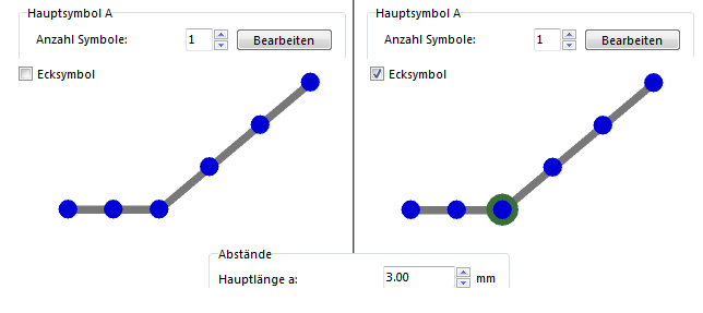
'''Ecksymbol'''<br> | |||
Ein Ecksymbol erscheint bei jedem '''[[Stützpunkte#Eckpunkt einfügen|Eckpunkt]]''' der Linie. Klicken Sie die '''Bearbeiten'''-Schaltfläche, um das Symbol mit Hilfe des '''[[Ein neues Punktsymbol erstellen#Symbol-Editor|Symbol-Editors]]''' zu bearbeiten. | |||
[[File:CornerSymbol.PNG]]<br> | |||
''Diese Abbildung ist leider nur in Englisch verfügbar.'' | |||
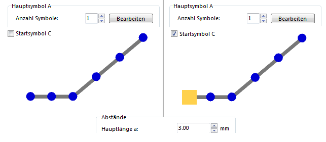
'''Startsymbol C'''<br> | |||
Ein Startsymbol erscheint beim Startpunkt der Linie. Klicken Sie die '''Bearbeiten'''-Schaltfläche, um das Symbol mit Hilfe des '''[[Ein neues Punktsymbol erstellen#Symbol-Editor|Symbol-Editors]]''' zu bearbeiten. | |||
[[File:StartSymbol.PNG]]<br> | |||
''Diese Abbildung ist leider nur in Englisch verfügbar.'' | |||
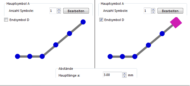
''' | '''Endsymbol D'''<br> | ||
Ein Endsymbol erscheint beim Endpunkt der Linie. Klicken Sie die '''Bearbeiten'''-Schaltfläche, um das Symbol mit Hilfe des '''[[Ein neues Punktsymbol erstellen#Symbol-Editor|Symbol-Editors]]''' zu bearbeiten. | |||
[[File:EndSymbol.PNG]]<br> | |||
''Diese Abbildung ist leider nur in Englisch verfügbar.'' | |||
[[File: | ===Beispiele=== | ||
[[File:Example.jpg]] '''[[Beispiel Stromleitung]]''' | |||
: Dieses Beispiel zeigt ein Liniensymbol mit Ecksymbolen. | |||
[[File:PowerLine.PNG|750px]] | |||
''' | [[File:Example.jpg]] '''[[Beispiel Gondelbahn]]''' | ||
: Dieses Beispiel zeigt ein Liniensymbol mit einem Haupt-, Start- und Endsymbol. | |||
[[File:CableCar.PNG|750px]] | |||
[[File:Example.jpg]] '''[[Beispiel Kantonsgrenze]]''' | |||
: Dies ist ein Beispiel für ein Liniensymbol mit einem speziellen Hauptsymbol. | |||
[[File:CantonBoundary.PNG|750px]] | |||
[[File:Example.jpg]] '''[[Beispiel Flächenbegrenzung]]''' | |||
: Dieses Beispiel zeigt ein Liniensymbol mit einem Punktsymbol zwischen den Strichen. | |||
[[File:AreaBoundary.PNG|750px]] | |||
[[File:Example.jpg]] '''[[Beispiel Geologisches Liniensymbol]]''' | |||
: Dies ist ein Beispiel für ein Liniensymbol mit einem Haupt- und Zusatzsymbol. | |||
[[File:GeologicalLine.PNG|750px]] | |||
[[File:Example.jpg]] '''[[Beispiel Gestrichelte Linie mit Punkten]]''' | |||
: Dies ist ein Beispiel für eine gestrichelte Linie mit Punkten in der Mitte jedes Hauptstrichs. | |||
[[File:DashedLineWithDots.PNG|750px]] | |||
''' | ===Double Line=== | ||
---- | |||
Double lines are primarily used for streets, where you have a left and a right border line filled or not filled with another color. If you need a center line (often used for highways) define a main line (note, that the color for the center line must be above the color for the infill in the '''[[Colors|Color Table]]'''). | |||
====Mode==== | |||
* ''' | Select the mode of the double line. You have the following options for a double line: | ||
* ''' | *'''Off''': No double line is shown. | ||
* ''' | *'''Full lines''': The two lines which form a double line are continuous. | ||
* ''' | *'''Left line dashed''': The left line is dashed. | ||
* ''' | *'''Right line dashed''': The right line is dashed. | ||
*'''All dashed''': Both lines are dashed. | |||
====Width==== | |||
Enter the distance between the two double lines in this field. If you use a fill color, this is the width of the filling between the two border lines. | |||
====Fill Color==== | |||
Check the '''On''' option, to activate the fill color. In the dropdown list a color of the '''[[Colors|Color Table]]''' can be chosen. The border of the filling is formed by the sidelines. The filling does not exceed those border lines, therefore there are often really small gaps between the sidelines and the filling. To avoid these gaps make use of the '''[[Create a New Line Symbol#Framing|Framing]]''' which is described later on this page. The advantage of a fill color is that for example street crossings are automatically cleared. To get that effect you must choose a fill color which is above the color of the side lines in the '''[[Colors|Color Table]]'''. Otherwise the infill cannot erase the side lines in the street crossings. | |||
====Left and Right Line==== | |||
'' | Assign a color from the '''[[Colors|Color Table]]''' to the left respectively the right sideline. Those can be colored individually and the '''Line width''' can be chosen distinctly as well. Choose 0 as a line width if you want to show the sideline for example only on the left side. | ||
[[File:DoubleLineHint.PNG]] | |||
====Dashed==== | |||
If you chose the '''Left line dashed''', '''Right line dashed''' or '''All dashed''' option as a double line mode, you can enter the dash and gap lengths in this part of the dialog. The value entered in the '''Distance a''' field defines the dash length and the value entered in the '''Gap''' field stands for the gap length. | |||
''' | ====Examples==== | ||
[[File:Example.jpg]] '''[[Example Minor Road]]''' | |||
: This is an example for a simple double lined symbol. | |||
[[File:MinorRoadNormal.PNG|750px]] | |||
[[File:Example.jpg]] '''[[Example Motorway]]''' | |||
: This is an example for a simple double lined symbol with activated, dashed main line. | |||
: [[File: | [[File:Motorway.PNG|750px]] | ||
[[File:Example.jpg]] '''[[Example National Park Boundary]]''' | |||
: This is an example of a line symbol with activated double line in the '''Right line dashed''' mode and the left line set to 0.00. | |||
[[File:NationalPark.PNG|750px]] | |||
''' | [[File:Example.jpg]] '''[[Example Dashed Minor Road]]''' | ||
: This is an example of a line symbol with dashed double line. | |||
[[File:MajorRoadMiddleLineFrameDashed.PNG|750px]] | |||
[[File:Example.jpg]] '''[[Example Three Lanes]]''' | |||
: This is an example of a line symbol with a double line, which does not appear as a borderline. | |||
[[File:Highway.PNG|750px]] | |||
[[File:Example.jpg]] '''[[Example Three Lanes Dashed]]''' | |||
: This is an example of a quite complex line symbol with a dashed double line, which does not appear as a borderline. | |||
[[File:TwoDashed.PNG|750px]] | |||
[[File:Example.jpg]] '''[[Example Power Line]]''' | |||
: This is an example for a line symbol with a double line without filling. | |||
[[File:PowerLine.PNG|750px]] | |||
===Decrease=== | |||
---- | |||
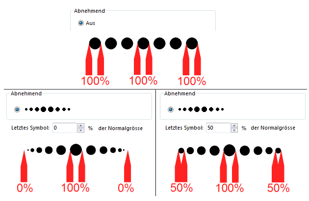
These features are primarily used for geological symbols with decreasing dots. | |||
Decide if defined symbols shall only decrease at one end or at both ends in the '''Decrease''' part of the tab. In the '''Last symbol''' field enter a value in percentage how much the symbols shall decrease towards the ends. The distance between the symbols is also decreased. However, the dashes of dashed lines are not decreased. Therefore, you should not use the '''Decrease''' function together with dashed lines. | |||
[[File:Decrease.PNG]] | |||
====Examples==== | |||
[[File:Example.jpg]] '''[[Example Geological Line Symbol]]''' | |||
: This is an example for a line symbol with decreasing ends on both ends. | |||
[[File:GeologicalLine.PNG|750px]] | |||
''' | [[File:Example.jpg]] '''[[Example Stone Embankment Top Edge]]''' | ||
: This is an example for a line symbol with decreasing ends on both ends. | |||
[[File:StoneEmbankmentTopEdge.PNG|750px]] | |||
===Framing=== | |||
---- | |||
Framing lines are normally used as a background to line objects. Often a framing line is used to block out (or cover) other objects. Note that the color of the framing line must be above the colors of the objects to be covered in the color table. | Framing lines are normally used as a background to line objects. Often a framing line is used to block out (or cover) other objects. Note that the color of the framing line must be above the colors of the objects to be covered in the color table. | ||
* '''Line color:''' Select the line color. | * '''Line color:''' Select the line color. | ||
| Zeile 173: | Zeile 271: | ||
* '''Line style:''' Select one of the 3 line styles with different line ends and line joins. | * '''Line style:''' Select one of the 3 line styles with different line ends and line joins. | ||
Choose a framing if you want to avoid small gaps between sidelines and filling. These occur, when using a '''Fill color''' with double lines. The framing must have the same color than the filling but must be at a lower position in the '''[[Colors|Color Table]]'''. In addition, they must be wider than the filling (for example width of filling plus half width of the sidelines). | |||
''' | ====Examples==== | ||
[[File:Example.jpg]] '''[[Example Railway]]''' | |||
: This is an example for a line symbol black framing under a white main line. | |||
[[File:DashedFraming.PNG|750px]] | |||
==Icon== | |||
Click the '''Icon''' button in the dialog to create an icon for the symbol. The '''Icon Editor''' appears. Read more about this editor in the '''[[Create a New Symbol#Icon Editor|Icon Editor]]''' article. | |||
---- | |||
: [[File:Camera.jpg|video available]][http://www.ocad.com/howtos/44.htm Different lines symbols] | |||
'''Create | Back to the '''[[Create a New Symbol]]''' page. | ||
Version vom 28. Januar 2013, 12:10 Uhr
Mit OCAD können Sie sehr komplexe Liniensymbole erstellen. Ausserdem kann uns der Symboleditor fast alle Zeichnungs- und Bearbeitungswerkzeuge zur Verfügung stellen, um Liniensymbole noch einfacher zu gestalten.
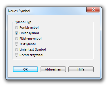
Wählen Sie den Neu-Menüpunkt im Symbol-Menü. Im Neues Symbol-Dialogfenster wählen Sie Liniensymbol aus, um ein neues Liniensymbol zu erstellen.
Der Liniensymbol-Dialog erscheint. Dieser besteht aus sechs Registerkarten:
- Hauptlinie: Passen Sie hier die Farbe, Strichdicke und Linienart an.
- Abstände: Passen Sie hier die Längen von gestrichelten Linien und die Unterbrüche an.
- Symbole: Hier können Sie Start-, End-, Zusatz- und Ecksymbole definieren.
- Doppellinie: Hier können Sie alle Eigenschaften einer doppelten Linie definieren (Farbe, Strichdicke, Linienart etc.).
- Abnehmend: Definieren Sie hier einen abnehmenden Linientyp.
- Freistellung: Hier können Sie Linien freistellen, sodass z.B. komplexe Linien andere Objekte trotzdem überdecken.
Hauptlinie
In der Hauptlinie-Registerkarte können Sie folgende Anpassungen vornehmen:
Symbolnummer
Geben Sie in diesem Feld eine Symbolnummer zwischen 0.001 und 999999.999 ein.
Symbolbeschreibung
Geben Sie dem Symbol eine Beschreibung (z.B. Eisenbahnlinie).
Vorzugszeichenwerkzeug
Sie können hier ein Vorzugszeichenwerkzeug wählen. Wenn das Symbol in der Symbolbox angewählt wird, wechselt OCAD automatisch in den entsprechenden Zeichnungsmodus. Wenn in der Dropdown-Liste Aus ausgewählt ist, bleibt OCAD beim Anwählen des Symbols im letzt aktiven Zeichnungsmodus.
Linienfarbe
Wählen Sie hier eine Linienfarbe der Hauptlinie. Die Dropdown-Liste enthält alle Farben, welche in der Farbtabelle definiert sind. Wenn keine Hauptlinie verwendet wird, ist es nicht nötig eine Linienfarbe zu definieren.
Strichdicke
Geben Sie in diesem Feld eine Strichdicke ein. Wenn Sie keine Hauptlinie anzeigen möchten, wählen Sie 0.00mm.
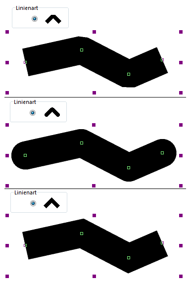
Linienart
Wählen Sie zwischen drei Linienarten aus. Die Linienenden und -ecken erscheinen jeweils in anderer Form.
Diese Abbildung ist leider nur in Englisch verfügbar.
Länge
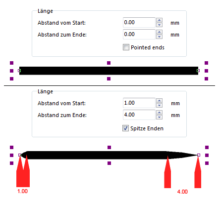
Geben Sie hier zwei Abstände ein:
- Abstand vom Start: Dieser Wert beschreibt den Abstand vom Linienanfang bis zum Hauptlinienanfang (dann wenn die Linie sichtbar wird).
- Abstand zum Ende: Dieser Wert beschreibt den Abstand vom Hauptlinienende bis zum Linienende (vom sichtbaren Linienende bis zum tatsächlichen Linienende).
Diese Abbildung ist leider nur in Englisch verfügbar.
Wenn Sie die Spitze Enden-Option aktivieren, erhält die Linie, über die Distanz der eben erwähnten Abstände, Spitzen.
Diese Abbildung ist leider nur in Englisch verfügbar.
Bahnlegung für den Orientierungslauf-Optionen
In Bahnlegungsprojekten steht Ihnen eine zusätzliche Option zur Verfügung, nämlich das Verwenden des Symbols als Pflichtstrecke. Besuchen Sie die Bahnlegungsobjekte hinzufügen-Seite für weitere Informationen.
Beispiele
- Dies ist ein Beispiel für eine einfache, durchgehende Linie.
![]() Beispiel Gestrichelte Linie mit Hintergrund
Beispiel Gestrichelte Linie mit Hintergrund
- Dies ist ein Beispiel, welches die Funktionen Abstand vom Start und Abstand zum Ende verdeutlichen.
- Dies ist ein Beispiel, welches die Funktionen Abstand vom Start und Abstand zum Ende verdeutlichen.
- Dies ist ein Beispiel für Spitze Enden.
Abstände
In dieser Registerkarte können Sie alle Parameter für gestrichelte Linien einstellen.
Abstände
Hauptlänge a
Diese Länge definiert die Länge des Hauptstriches (siehe Abbildung im oberen Teil des Dialogs, der Hauptstrich ist mit dem Buchstaben a markiert). Für gepunktete Linien geben Sie hier die Distanz zwischen den Punkten ein.
Endlänge b
Diese Länge definiert die Länge der Start- und Endstriche (siehe Abbildung im oberen Teil des Dialogs, die Endstriche sind mit dem Buchstaben b markiert). Für gepunktete Linien sollten Sie hier 0 eingeben, um sicherzustellen, dass die Linie mit einem Punkt und nicht einer Lücke beginnt. Für Linien mit Punkten drauf geben Sie hier die Distanz vom Linienanfang bis zum ersten Punkt auf der Linie ein.
![]() Die Endlänge wird auch vor und nach einer Ecke der Linie benutzt.
Die Endlänge wird auch vor und nach einer Ecke der Linie benutzt.
mindestens X Unterbrüche/Symbole
Sie können hier eine minimale Anzahl (maximal 2) Lücken oder Symbole (wenn ein Hauptsymbol definiert ist) angeben, welche eine Linie beinhalten muss. Wenn Sie wollen, dass eine gestrichelte Linie immer eine Lücke hat (egal wie kurz sie ist), wählen Sie hier 1.
Unterbrüche
Unterbruch C
Dies ist der Hauptunterbruch und der Wert in diesem Feld definiert dessen Länge (siehe Abbildung im oberen Teil des Dialogs, der Hauptunterbruch ist mit dem Buchstaben C markiert).
Unterbruch D
Sie können einen zusätzlichen Unterbruch zum Hauptstrich fügen. Definieren Sie eine Länge für diesen im entsprechenden Feld (siehe Abbildung im oberen Teil des Dialogs, der Unterbruch D ist mit dem Buchstaben D markiert).
Unterbruch E
Sie können einen zusätzlichen Unterbruch den Endstrichen hinzufügen. Definieren Sie eine Länge für diesen im entsprechenden Feld (siehe Abbildung im oberen Teil des Dialogs, der Unterbruch E ist mit dem Buchstaben E markiert).
Beispiele
- Dieses Beispiel zeigt eine gestrichelte Linie mit einer Hauptlänge von 2.0mm, Endlängen von 1.0mm und einem Hauptunterbruch von 0.5mm.
- Dies ist ein Beispiel für eine gepunktete Linie mit einer Hauptlänge von 1.0mm.
![]() Beispiel Gestrichelte Linie mit Punkten
Beispiel Gestrichelte Linie mit Punkten
- Dieses Beispiel zeigt eine gestrichelte Linie mit einem Punkt in der Mitte jedes Strichs.
Symbols
Fügen Sie ein Symbol zu Ihrer Linie hinzu, um diese noch einzigartiger zu machen. Dieses Punktsymbol kann ein einfacher Punkt oder auch eine komplexe Struktur sein.
Hauptsymbol
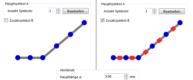
Im Hauptsymbol A-Bereich des Dialogs können Sie ein Hauptsymbol definieren. Das Hauptsymbol erscheint an jedem Hauptunterbruch, welcher in der Abstände-Registerkarte des Dialogs definiert wird.
Anzahl Symbole
Das Hauptsymbol kann aus mehr als einem Symbol bestehen. Es kann aus bis zu fünf gleichen Symbolen bestehen.
Bearbeiten-Schaltfläche
Um die Symbole, welche im oberen Paragraphen beschrieben wurden, zu bearbeiten, klicken Sie auf die Bearbeiten-Schaltfläche. Der Symbol-Editor erscheint, wo Sie ein Symbol mit fast allen Zeichnungs- und Bearbeitungswerkzeugen von OCAD zeichnen können. Lesen Sie den Symbol-Editor-Artikel, um weitere Informationen zu erhalten. Dort finden Sie auch einen speziellen Paragraphen für strukturierte Linien.
Abstand
Der Wert, der in das Abstand-Feld eingegeben wird, definiert den Abstand zwischen den individuellen Symbolen, ausser die Anzahl Symbole beträgt 0 oder 1.
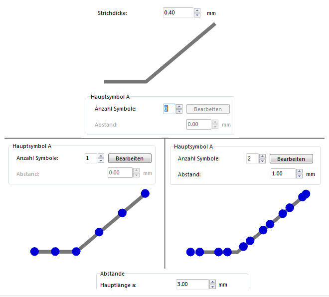
Diese Abbildung ist leider nur in Englisch verfügbar.
Andere Symbole
Zusatzsymbol B
Ein Zusatzsymbol erscheint an der Stelle des Unterbruchs D, welcher in der Abstände-Registerkarte dieses Dialogs definiert wurde. Demnach erscheint das Zusatzsymbol genau in der Mitte zweier Hauptsymbole. Klicken Sie die Bearbeiten-Schaltfläche, um das Symbol mit Hilfe des Symbol-Editors zu bearbeiten.
Diese Abbildung ist leider nur in Englisch verfügbar.
Ecksymbol
Ein Ecksymbol erscheint bei jedem Eckpunkt der Linie. Klicken Sie die Bearbeiten-Schaltfläche, um das Symbol mit Hilfe des Symbol-Editors zu bearbeiten.
Diese Abbildung ist leider nur in Englisch verfügbar.
Startsymbol C
Ein Startsymbol erscheint beim Startpunkt der Linie. Klicken Sie die Bearbeiten-Schaltfläche, um das Symbol mit Hilfe des Symbol-Editors zu bearbeiten.
Diese Abbildung ist leider nur in Englisch verfügbar.
Endsymbol D
Ein Endsymbol erscheint beim Endpunkt der Linie. Klicken Sie die Bearbeiten-Schaltfläche, um das Symbol mit Hilfe des Symbol-Editors zu bearbeiten.
Diese Abbildung ist leider nur in Englisch verfügbar.
Beispiele
- Dieses Beispiel zeigt ein Liniensymbol mit Ecksymbolen.
- Dieses Beispiel zeigt ein Liniensymbol mit einem Haupt-, Start- und Endsymbol.
- Dies ist ein Beispiel für ein Liniensymbol mit einem speziellen Hauptsymbol.
- Dieses Beispiel zeigt ein Liniensymbol mit einem Punktsymbol zwischen den Strichen.
![]() Beispiel Geologisches Liniensymbol
Beispiel Geologisches Liniensymbol
- Dies ist ein Beispiel für ein Liniensymbol mit einem Haupt- und Zusatzsymbol.
![]() Beispiel Gestrichelte Linie mit Punkten
Beispiel Gestrichelte Linie mit Punkten
- Dies ist ein Beispiel für eine gestrichelte Linie mit Punkten in der Mitte jedes Hauptstrichs.
Double Line
Double lines are primarily used for streets, where you have a left and a right border line filled or not filled with another color. If you need a center line (often used for highways) define a main line (note, that the color for the center line must be above the color for the infill in the Color Table).
Mode
Select the mode of the double line. You have the following options for a double line:
- Off: No double line is shown.
- Full lines: The two lines which form a double line are continuous.
- Left line dashed: The left line is dashed.
- Right line dashed: The right line is dashed.
- All dashed: Both lines are dashed.
Width
Enter the distance between the two double lines in this field. If you use a fill color, this is the width of the filling between the two border lines.
Fill Color
Check the On option, to activate the fill color. In the dropdown list a color of the Color Table can be chosen. The border of the filling is formed by the sidelines. The filling does not exceed those border lines, therefore there are often really small gaps between the sidelines and the filling. To avoid these gaps make use of the Framing which is described later on this page. The advantage of a fill color is that for example street crossings are automatically cleared. To get that effect you must choose a fill color which is above the color of the side lines in the Color Table. Otherwise the infill cannot erase the side lines in the street crossings.
Left and Right Line
Assign a color from the Color Table to the left respectively the right sideline. Those can be colored individually and the Line width can be chosen distinctly as well. Choose 0 as a line width if you want to show the sideline for example only on the left side.
Dashed
If you chose the Left line dashed, Right line dashed or All dashed option as a double line mode, you can enter the dash and gap lengths in this part of the dialog. The value entered in the Distance a field defines the dash length and the value entered in the Gap field stands for the gap length.
Examples
- This is an example for a simple double lined symbol.
- This is an example for a simple double lined symbol with activated, dashed main line.
![]() Example National Park Boundary
Example National Park Boundary
- This is an example of a line symbol with activated double line in the Right line dashed mode and the left line set to 0.00.
- This is an example of a line symbol with dashed double line.
- This is an example of a line symbol with a double line, which does not appear as a borderline.
- This is an example of a quite complex line symbol with a dashed double line, which does not appear as a borderline.
- This is an example for a line symbol with a double line without filling.
Decrease
These features are primarily used for geological symbols with decreasing dots.
Decide if defined symbols shall only decrease at one end or at both ends in the Decrease part of the tab. In the Last symbol field enter a value in percentage how much the symbols shall decrease towards the ends. The distance between the symbols is also decreased. However, the dashes of dashed lines are not decreased. Therefore, you should not use the Decrease function together with dashed lines.
Examples
![]() Example Geological Line Symbol
Example Geological Line Symbol
- This is an example for a line symbol with decreasing ends on both ends.
![]() Example Stone Embankment Top Edge
Example Stone Embankment Top Edge
- This is an example for a line symbol with decreasing ends on both ends.
Framing
Framing lines are normally used as a background to line objects. Often a framing line is used to block out (or cover) other objects. Note that the color of the framing line must be above the colors of the objects to be covered in the color table.
- Line color: Select the line color.
- Line width: Enter here the line width. Enter 0 here if no framing line should be drawn.
- Line style: Select one of the 3 line styles with different line ends and line joins.
Choose a framing if you want to avoid small gaps between sidelines and filling. These occur, when using a Fill color with double lines. The framing must have the same color than the filling but must be at a lower position in the Color Table. In addition, they must be wider than the filling (for example width of filling plus half width of the sidelines).
Examples
- This is an example for a line symbol black framing under a white main line.
Icon
Click the Icon button in the dialog to create an icon for the symbol. The Icon Editor appears. Read more about this editor in the Icon Editor article.
Back to the Create a New Symbol page.


